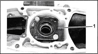
Check the alignment of the gearcase housing on gearcase assemblies that have experienced impact damage and/or internal bearing and gear failure.
Distorted gearcase housings affect driveshaft to propshaft alignment and gear alignment. Failure to properly identify distorted gearcase housings can result in replacement gear failure. This type of failure is not covered by warranty.
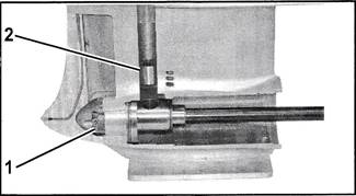
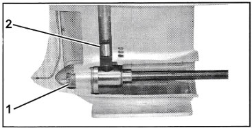
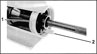
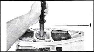
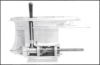
This gauge kit assembles to the forward bearing housing of a standard rotation gearcase and driver handle, P/N 311880 (existing tool). Assemble as indicated to check all V6 gearcase housings (1979 and newer 4 hole water inlet, "0" and "L" types; and "M" and "XP" types). Refer to P&A Bulletin No. 2002-02 to properly identify gearcase types.
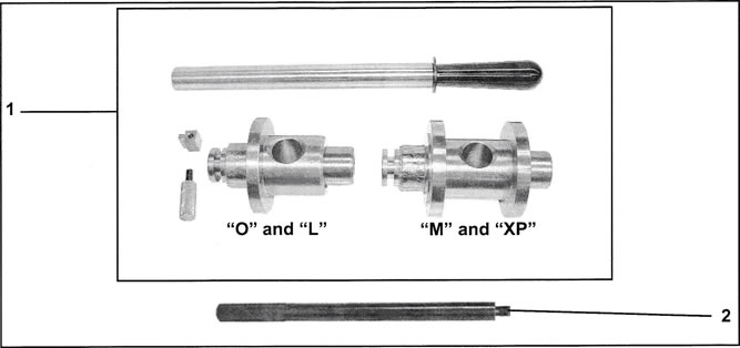
- Gearcase Alignment Gauge Kit, P/N 5006349
- Driver Handle, P/N 311880