| Date: July, 2005 | No. 2005-03(S) |
| MODELS: 2005 Evinrude® E-TEC 200-250 HP | SUBJECT:Cylinder Head Modification to Eliminate Low Speed Overheat |
Dear Evinrude/Johnson. Dealers: This communication is to inform Evinrude and Johnson dealers of a change to the cylinder head on 2005 Evinrude E-TEC 200-250 HP models. Outboards with serial number 5109291 or higher are built with this feature. In certain operating conditions, a low speed over-heat can occur. The following cylinder head modification will eliminate persistent low speed overheat conditions. A machined passage was added to the top of the cylinder head, adjacent to the seat for the thermostat cover. This new machined passage allows air to vent from the top of the thermostat chamber to the top pressure valve passage of the cylinder head. This feature can be added to 2005 Evinrude E-TEC 200-250 HP models built prior to serial number 5109291. Adding this feature provides improved venting of the thermostat chamber and improves thermostat operation. PROCEDURE |
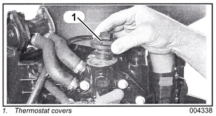
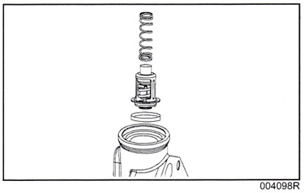
Remove the thermostat spring and thermostat assembly.
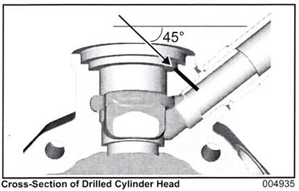
IMPORTANT: Carefully place a paper towel or equivalent in cylinder head opening to prevent metal chips from entering the cooling passages of cylinder head. IMPORTANT: Apply grease to the full length of drill bit to capture metal chips during drilling. Use a 1/8 in. drill bit. Center drill bit on pressure valve passage. Drill a 1/8 in. (0.3 mm) hole at a 45° angle into the second step of the cylinder head.
|
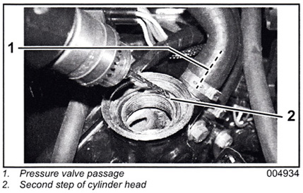
Drill until the drill bit enters pressure valve passage, through the brass hose fitting.
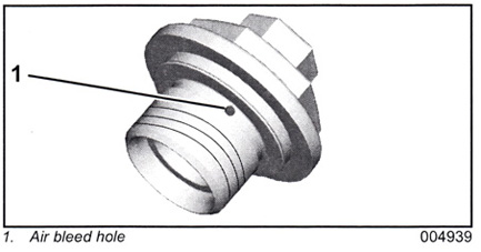
Remove the paper towel from the cylinder head. Clear any chips or debris from area using compressed air, and reinstall the original thermostat assembly and thermostat spring. Inspect thermostat O-ring. Replace, if necessary. Carefully coat threads of each head thermostat cover with Gasket Sealing Compound. Install and and tighten the cover to a torque of 120 to 144 in. lbs. (13.6 to 16.3 N-m). IMPORTANT: Use caution when coating thermostat cover threads to endure air bleed holes are not coated or obstructed.
Start the outboard and check thermostat cover area for water leaks. |
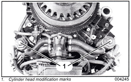
Identification Procedure Every outboard that has had the cylinder head modification procedure must be easily identified. Use a white permanent marker or 'paint to mark the top of the thermostat cover to indicate the machined hole is present.
ADDITIONAL INFORMATION Dealers without online claim processing can submit a standard warranty claim form. Labor will be paid in accordance with the established warranty labor rates listed in the current dealer warranty database. BRP will credit dealers for repairs performed up to 12 months from the date this bulletin is issued. |