OMC 386658 Piston Cradle and Pin Kit
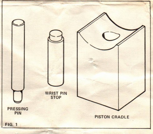
The OMC piston cradle and pin kit supports a piston while the wrist pin is pressed out or installed. The curved cradle matches the piston skirt, helping reduce distortion during service. This example survives with its OMC Parts & Accessories box, all three metal components, and the original factory instruction sheet. The kit was purchased during a clearance sale for approximately $2.

Kit contents and individual part numbers
| Part number | Component | Purpose |
|---|---|---|
| 319917 | Wrist pin stop | Fits the drilled hole in the cradle and limits wrist pin travel during installation. |
| 319919 | Piston cradle | Supports the piston skirt during wrist pin removal and installation. |
| 319920 | Pressing pin | Transfers press force to the wrist pin. |
Applications and purpose
The original tool listing identifies this kit for 1974-1977 Johnson and Evinrude 9.9 and 15 HP outboards. The factory instruction sheet describes use with standard-size pistons on 9.9 and 15 HP outboards. It does not establish compatibility with every later model or with oversized pistons.
Factory precaution: Before each use, inspect the cradle radius for nicks, burrs, and grit. Remove imperfections that could damage the piston during pressing. The close-tolerance cradle is intended to minimize piston distortion.
Original OMC Special Tools Instruction Sheet
IMPORTANT - SAVE THIS SHEET FOR FUTURE REFERENCE
INSTRUCTIONS FOR PISTON CRADLE AND PIN KIT PART NUMBER 386658
This piston cradle should be used when removing and installing the wrist pin in standard size pistons used on 9.9 and 15 H.P. outboards. The close tolerance radius on the piston cradle provides the proper support to minimize distortion. This tool set was designed to be used with an arbor press.
The cradle radius should be examined before every use to make sure it is free of nicks, burrs, grit, etc. which could damage the piston during the pressing operation. Remove any such imperfections with a file.
WRIST PIN REMOVAL
- Use an awl to pry the wrist pin retaining rings out of the pistons.
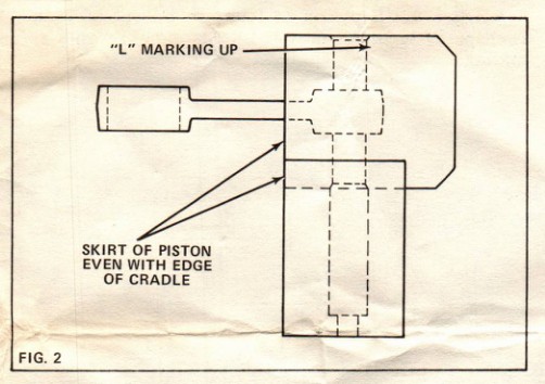
- Place the piston and rod assembly on the cradle. The side of piston marked “L” must be up and the skirt of piston must be aligned with edge of cradle (wrist pin centered on drilled hole in cradle). See figure 2.
- Place the pressing pin atop the wrist pin and press pin out of piston.
WRIST PIN INSTALLATION
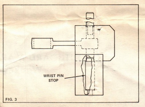
- Place wrist pin stop in drilled hole in cradle. The stop will prevent you from pressing the wrist pin beyond the piston's lower retaining ring groove.
- Place piston on cradle with piston side marked “L” facing up. Skirt of piston should be even with edge of cradle.
- Position connecting rod in piston and insert wrist pin into piston's loose side and through rod.
- Place pressing pin atop wrist pin and press in until wrist pin hits the wrist pin stop. See figure 3.
- Install wrist pin retaining rings using cone (special tool #319945) and driver (special tool #319944). Correctly installed, end gap of retaining rings will be toward skirt end of piston.
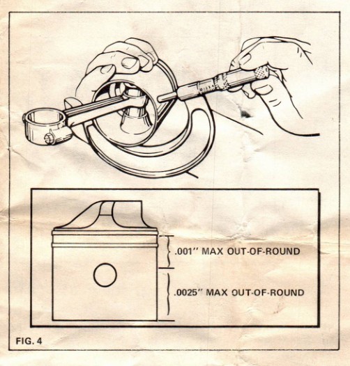
- Use a micrometer to check the piston for out-of-roundness. Maximum out-of-round permitted is:
- .001" between bottom of upper ring land and top of wrist pin.
- .0025" between top of wrist pin and bottom of skirt.
Historical notes and related tools
The factory sheet is dated October 1974 and identifies this assembly as part number 386658. It was supplied with a piston cradle, pressing pin, and wrist pin stop. The original kit shown above was purchased during a clearance sale for approximately $2.
Additional tools named in the instructions: 319944 wrist pin retaining ring driver and 319945 cone.
The factory instructions above have been transcribed as searchable HTML, with the four original illustrations extracted from the scan. Paragraphs and procedures follow the original document; figures are placed beside the relevant instructions. The photograph and historical notes are editorial material, separate from the factory sheet.