REPLACING MAGNETO DRIVING BELT
To replace the magneto driving belt (time the magneto) proceed as follows:
- Remove the manual starter housing.
- Remove the old belt - sever with wire cutters if unfit for use.
- Detach cover plate from the magneto pulley.
- Carefully install new belt over the flywheel - the belt is large enough to permit doing so.
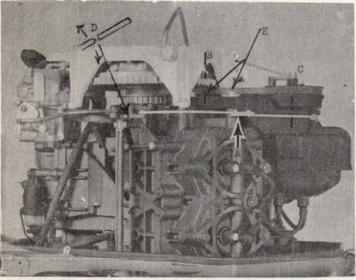
- Note timing "marks" or embossings at positions b, c and d.
- Replace manual starter housing.
- Turn flywheel until timing marks at position B fall in line - embossing on the starter housing, score mark on the flywheel and score mark on the cylinder casting provided for this purpose.
- Align timing marks at position "C" - if linkage adjustment at position "A" has not been disturbed, turn speed control grip or lever until the timing mark embossed on the breaker point housing falls in line with the timing mark on the magneto bracket. Turn magneto pulley in clock wise direction to align all three timing marks as in position "C".
- "Slip" belt on over the magneto pulley. Sprockets on both pulleys and on inside face of the belt prevent slippage to retain proper magneto (spark) timing.
- Re
- Replace magneto pulley cover. Proper belt tension is achieved by loosening screws (3) indicated by position "E" to permit "in" and "out" movement of the magneto assembly - tension is increased by moving "out", lessened by moving "in". Belt tension is correct when sides can be compressed to 3 3/8" to 3 1/2" with light pressure between the thumb and forefinger. Tighten screws to secure position of the magneto assembly.
- However, in event of having "disturbed" linkage adjustment at position "A", alignment of two additional timing marks is required - at position "D".
- With linkage adjusting screws (a) loose, turn speed control grip or lever until timing mark embossed on the speed control "arm" aligns with a like embossing on support casting - position "D".
- Align all three timing marks at position "C" as shown. Tighten linkage screws to secure linkage adjustment.
P. S. - Note - The spark terminals do not "pull" out of the distributor cap - they are threaded and must be turned "in" & "out".
Very truly yours,
Manager - Service Promotion
JOHNSON MOTORS
Arvid Olson
Arvid OlsonManager - Service Promotion