
August 20, 1959
Bulletin No. SB-732
SUBJECT: Modifying the 50 H.P. Carburetor to 1959 Specifications.
Since the 1959 50 H.P. Carburetors have made such a marked improvement in engine operation,
providing better idling qualities and decreased fuel consumption, this bulletin is being
issued to cover the parts required and the procedure necessary to modify the 1958 carb-
uretors to 1959 specifications. To convert the 1958 carburetors the following parts must
be ordered from your parts distributor.
Parts Necessary:
QTY DESCRIPTION PART NUMBER
2 Air restrictors 307024
2 Orifice plugs 307065
2 Lead shots 304201
1 Hinge pin 302661
2 Venturi to body gaskets 305222
1 Cover to body gasket 305218
2 Venturi 377156
Procedure:
1. Remove the carburetor from the powerhead. Disassemble and modify as follows.
2. Remove the carburetor cover and choke valve assembly from the carburetor body and
plug assembly. Take out the hinge pin 302661 and remove the float. Remove the two
venturi and high speed tube assemblies from the carburetor body.
3. Remove the two drain screw plugs part 303125 and retap the holes with a 1/4-20 tap,
7/16" to 1/2" deeper. Wash the carburetor body in a cleaning solvent and blow out with
air pressure to remove any chips or dirt that may remain in the passages.
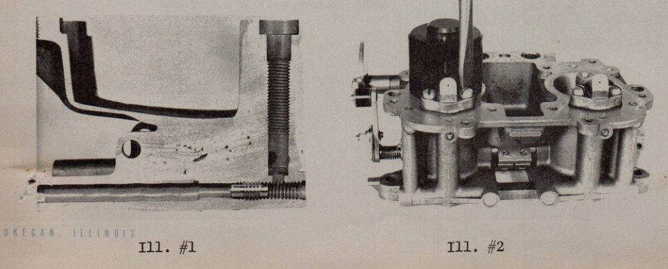
4. Install the orifice plugs part 307065 in the carburetor body (See Ill. 1) screw
the orifice to the bottom of the tapped hole. (This orifice must be screwed in
beyond the high speed needle hole). Use sealer on the drain screw plugs part
303125, and replace them tightly in the carburetor body.
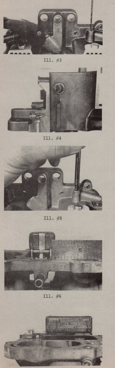
5. Install the new venturi using new gaskets part 305222.
When replacing the venturi, locating gage 378014 must be
used to center them properly. (See Ill. #2)
6. Drill a hole with a #46 drill in each lead shot 304201
found in the top cover. Remove the shot by threading a
small screw into the hole, and with a pair of side cutting
pliers, lift out the shot. (See Ill. #3). Be careful not
to mar or scuff the edge on the hole as this serves as
a seat and seal.
7. Before installing the new air restriction part 307024
deburr the end. Clean out the hole that the restrictor
fits into and check to make certain that it is 9/16" deep.
(See Ill. #4) after the air restriction is in place, install
the lead shots part 304201 and seat them in place with a
punch. (See Ill. #5) If the shot is seated correctly the
restriction 307024 will be free to float back and forth
and extend through the hole 1/64" to 1/32".
8. Replace the float using a new hinge pin as the original
may be worn and thus too short. Adjust the float arm
hinge #305223 so that it is at a 90 degree angle to the
machined surface of the carburetor cover and choke valve
assembly. (See Ill. #6) Make certain that there are no
grooves worn in the float valve and seat assembly 375918.
If there are, replace with a new assembly.
9. When installing the float and float arm assembly
#377164 make certain that the float is parallel to the
machined surface of the carburetor cover and choke valve
assembly when held in an inverted position. (See Ill. #7)
10. Assemble carburetor cover to lower body using new
gasket part 305218. Check out the solenoid and assemble
the carburetor to the engine. Adjust the carburetor
according to Service Bulletin #665.
With these modifications properly made, engine operation
will be greatly improved with better idling qualities, and
making it impossible to use excessive fuel through an
incorrectly adjusted high speed needles.
JOHNSON MOTORS
Jack Penland
Service Department
NOTE: Post on your 50 H.P. index.
JP:eb
8-20-59
Jack Penland