
September 24, 1959
Bulletin No. SB-739
Subject: Synchronizing Carburetor and Magneto 75 H.P. Series Engines.
Due to certain changes in the carburetor and
magneto synchronizing linkage on the 75 H.P.
series engines, the same procedure as used for
synchronizing the 50 H.P. series engines cannot
be used. The proper procedure for synchronizing
carburetor and magneto on the 75 H.P. series
engines is as follows:
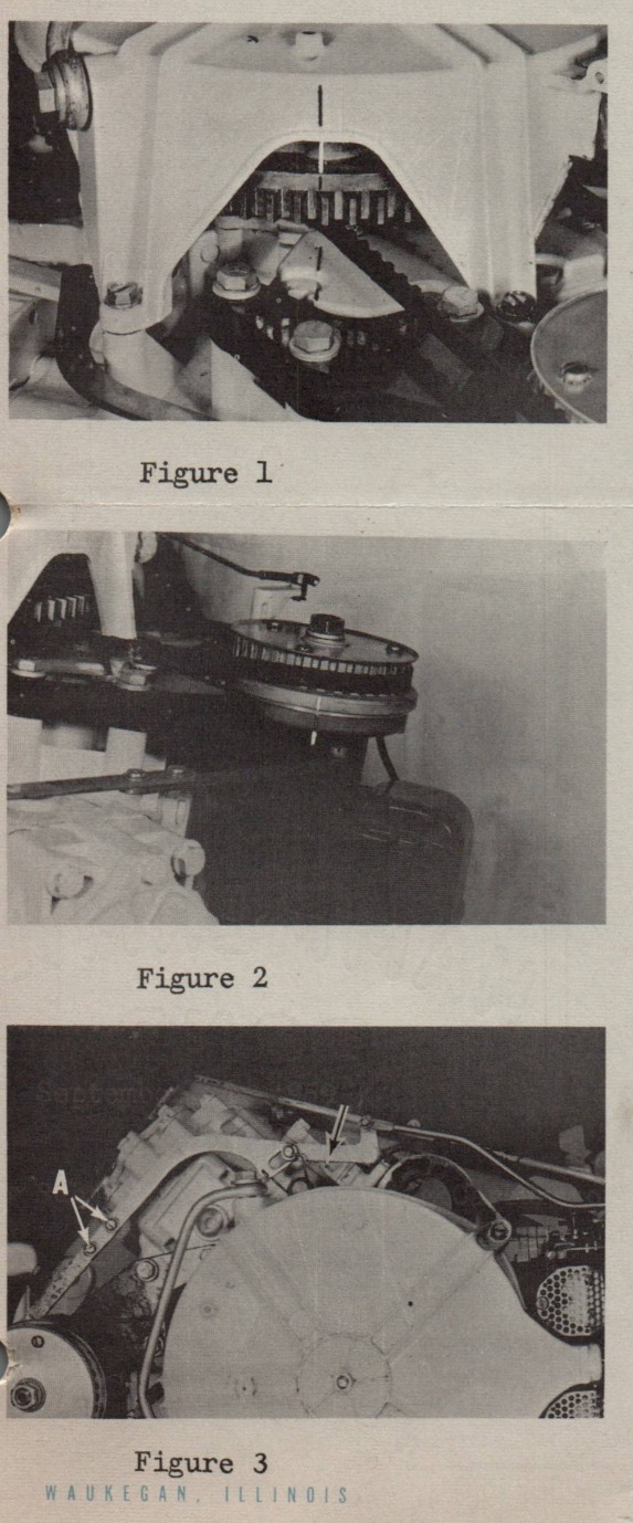
1. Make sure the magneto is timed properly with
the crankshaft by the timing belt. Align timing
marks on starter housing, flywheel and top of
cylinder (Fig. 1). At this point the timing marks
on the magneto bracket and the magneto pulley
should be in perfect alignment (Fig. 2). If
these timing marks do not align proceed to time
the magneto belt in accordance with Service
Bulletin #607.
2. Place the engine in forward gear and fully
advance the magneto by grasping the magneto
body. With the magneto in this position
the control shaft arm should be perfectly
parallel with the diamond shaped boss on
the cylinder casting (See arrow Fig. 3).
If the control shaft arm is not in alignment
with the diamond shaped boss, loosen
the linkage adjusting screws (letter "A"
Fig. 3) and make the necessary adjustment.
Retighten the linkage adjusting screws.
over
Page 2
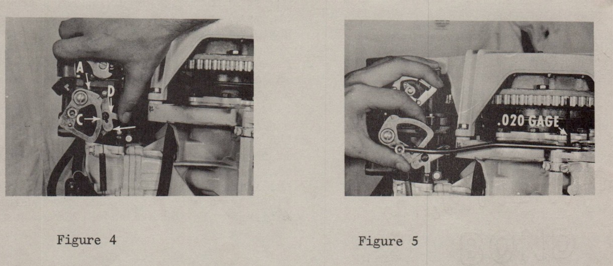
3. Check and/or readjust the position of the throttle arm with respect to the
position of the cam follower assembly (Fig. 4). Remove carburetor synchronizing
rod to gain easy access to adjusting screw "C". (NOTE - there are two set screws
securing the synchronizing rod. Remove the outer locking set screw to gain
access to the inner screw which secures the rod.) Loosen screw "C". Turn
throttle cam "A" to position where synchronizing score mark falls in line with
center of cam follower roller - at point of contact with cam contour. With thumb
bearing against arm "D", move arm "D" to the limit of its travel in direction
indicated by arrow. Make sure the cam roller contacts the cam at the score
mark. Tighten screw "C" to secure arm "D".
4. Place engine in forward gear. Advance the throttle lever to full open position.
Place a .020 feeler gage between the control shaft arm and the full throttle stop
on the cylinder casting (Fig. #5.).
5. With the throttle fully advanced and feeler gage in position (Paragraph #4)
proceed as follows. Replace the carburetor synchronizing rod through the pivot
pin. Fully open the carburetor by grasping the throttle cam with the thumb
and fore finger (Fig. #5). Tighten the set screw in the pivot pin securely.
Replace the locking set screw.
6. Remove the feeler gage and work the throttle to make sure that the throttle
arm is opening fully against the carburetor stop boss. NOTE - The purpose of
using the .020 feeler gage is to compensate for any slack or lost motion in
the linkage.
JOHNSON MOTORS
Jack Penland
Jack Penland
Service Department
JP:eb
NOTE: Post on your V4 index.