Johnson Service Bulletin SB-745 - Automatic Choke Service and Adjustment
November 11, 1959. Troubleshooting and adjustment procedure for the automatic chokes on Johnson 40 and 75 HP electric-starting engines.
November 11, 1959
Bulletin SB-NO.745
Subject: 40 and 75 H.P. AUTOMATIC CHOKE - SERVICE AND ADJUSTMENT.
The automatic chokes on the 40 and 75 H.P. electric
starting engines are preset at the factory for best
overall performance. If performance of the auto-
matic choke is not satisfactory, the following
procedure for locating the difficulty must be used.
1. Check choke valve shaft for binding:
Binding of the choke valve shaft can be corrected
by lubricating the bushing with light machine oil
or by straightening the shaft if it has been
accidentally bent. If the binding cannot be corrected
by oiling or straightening, it will be necessary
to replace the shaft (always use new screws when
reinstalling either throttle or choke butterfly
valves). Make certain that these screws are
properly staked to prevent loosening. Before
loosening any screws and/or removing the choke
assembly, read item #2 below.
2. Check choke assembly.
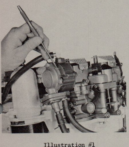
With a scriber, mark the position of the choke
assembly with respect to the water chamber -
(illustration #1). Remove the three choke assembly
attaching screws and remove the choke assembly
from the water chamber. Inspect the choke assembly
for loose, distorted or broken bimetal thermal
element. If any of these conditions exist the choke
assembly must be replaced. Check the choke assembly
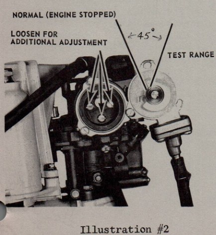
shaft for movement by turning the shaft clockwise as
viewed from the bimetal side (illustration #2). The
shaft should rotate through an angle of approximately
45° before reaching the internal stop. When the
shaft is released it should return to the original
position without binding. If it does not return
without binding, the choke assembly must be replaced.
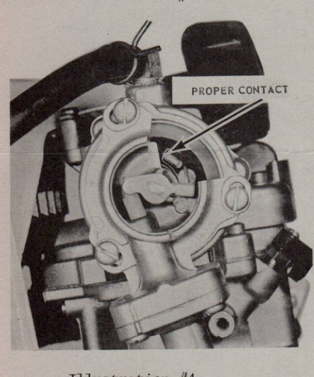
When reinstalling the choke assembly, make sure that
the hook on the bimetal element is properly positioned
on the chokeshaft lever (bimetal must contact left
hand side of arm (illustration #4). If items #1 and
#2 do not locate the source of the trouble, proceed
with item #3.
Page 2
3. Engine Warm-up.
This requires running the engine for a
minimum of ten minutes at not less than one-half
full power to stabilize engine temperature. Note-
To obtain correct operation of the automatic choke,
the engine temperature control thermostat must be
functioning properly. If the thermostat is blocked
open, the engine will run cool and the choke will
be too rich on the follow-through after the engine
starts. The automatic choke water jacket temperature,
after warm-up, is uncomfortable to the touch. After
engine warm up proceed with the following steps.
4. Place the manual choke lever in "OFF" position:
5. Adjust carburetor needle valves:
Operate engine at full power and adjust the
high speed needle valves. Return to idle and adjust
the low speed needle valves. Recheck idle adjust-
ments after engine has idled 3 or 4 minutes and
correct if necessary. Do not proceed to the next
step until the engine is operating smoothly.
6. Place the manual control choke lever in the
"Automatic" position:
This should result in no change in the operation
of the engine through the speed range. If the operat-
ion of the engine does change do not attempt any
adjustments of the automatic choke at this point,
but proceed to the next step.
7. Check position of choke shaft arm:
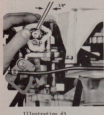
With a warm engine idling at approximately
600 R.P.M., push the choke shaft arm on the manual
override end of the choke shaft to the full open
position (illustration #3). Release the choke
shaft arm and measure the amount of motion with a
7/32" diameter pin attached to the arm. This
movement can be less than, but must not exceed 1/8
inch. If the motion exceeds 1/8" over choking will
take place, and the following should be checked.
a. Check vacuum line between choke assembly and manifold
for leaks and/or obstructions.
b. If no trouble is located under (a) proceed with step #8.
Page 3
8. Adjust Choke assembly:
If, after the preceding checks and adjustments have been made, the choke
is too rich or too lean, loosen the three screws which attach the choke assembly
to the water chamber and rotate in the direction indicated on the choke body.
If this is not sufficient adjustment, an additional amount of adjustment, may
be obtained by loosening the three screws which hold the water chamber to the
carburetor (illustration #2) and rotating it in the direction required as
indicated by the arrow on the choke body. Before making any of these latter
adjustments, mark original location of choke assembly and water chamber with a
scriber for reference purposes. When reinstalling choke assembly make sure that
the hooked end of the bimetal thermal element is properly positioned on the
choke shaft arm (bimetal must contact the left hand side of arm illustration #4).
Be sure to tighten all screws after making final adjustments. If the motion
described in step #7 can't be brought into the correct position thru the above
adjustments, the choke assembly must be replaced.
Never attempt to adjust the choke without:
a. Adjusting the carburetor needle valves properly.
b. Making sure that engine temperature control is
functioning properly.
c. Making sure that engine temperature is normal.
NOTE: When replacing the 40 H.P. shroud it is possible to knock the manual
choke lever in the "ON" position. Check after shroud is in place.