SERVICE MGR.
SALES MGR.
PARTS MGR.
SERVICE MGR.
SUBJECT: FLYWHEEL REMOVAL 40 H.P. MODELS.
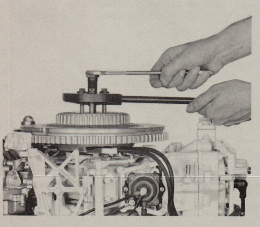
Recently you were advised concerning the availability of a new universal flywheel puller. (Refer to Service Bulletin SB-748.) It is suggested that the basic procedure outlined be followed to achieve satisfactory results with the new puller, when removing the flywheel of the 40 H.P. model engine.
- Remove the flywheel nut.
- Turn the large center screw of the puller to its outer limits. Attach the puller to the flywheel with the special hardened screws provided. (Make certain that the three attaching screws are threaded into the flywheel completely.)
- Turn down the large center screw until it contacts the crankshaft. With a wrench (figure #1) tighten the screw securely.
Page 2
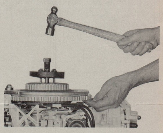
- Lift up on the rim of the flywheel to absorb shock, and strike the end of the puller screw sharply with a hammer. (Figure #2) If this fails to loosen the flywheel from the crankshaft, repeat steps 3 and 4 until it does. Note - be sure to lift on the rim of the flywheel (figure #2) to absorb shock and avoid possible damage to the powerhead.
The procedure in step #4 is required on the 40 H.P. engine due to the 100 ft. lbs. torque tension applied to the flywheel nut on assembly. This same procedure may be used, if necessary, to loosen a tightly set flywheel on other model engines.
Very truly yours,
JOHNSON MOTORS
Jack Penland
Jack Penland
Service Department
JP:eb
NOTE: POST ON YOUR RD INDEX