May 10, 1960
Bulletin No. SB-783
SUBJECT: GENERATOR CHARGING CIRCUIT MAINTENANCE AND CHECKS
The charging system supplies electric power for the electrical accessories and to keep
the battery charged. It includes the battery, ammeter, generator, regulator and the
wiring which connects these units.
The regulator controls the amount of electricity produced by the generator. It contains
three electro-magnetic devices - first, to automatically connect the generator to the
battery when the generator is operating fast enough to charge the battery and to dis-
connect the generator from the battery when the generator slows or stops, thus pre-
venting discharge of the battery through the generator - second, to limit the maximum
current output of the generator to a value that is safe for the generator - third, to
limit the voltage output of the generator to a value that will be safe for the battery,
radio and other accessories.
The charging system requires no periodic maintenance except to see that all connections
are clean and tight. All wiring and connections should be inspected frequently for
looseness and corrosion. This inspection should include cleaning of terminals in the
cable connector plug as well as the pins on the mating receptacle. Use care not to
over tighten the terminal nuts at the generator and ammeter as too much force will
twist off the terminals. All terminal nuts and screws should have lockwashers and be
snug. The connections at the terminal block in the junction box should be tight and
clean. Do not overlook the ground connections in the terminal box, the terminal box
cover and at the cable connector.
Check the generator mounting bolt nuts for tightness (70 to 80 in pounds).
VOLTMETER CHECKS
These tests are not needed unless there is some indication that the generator and
regulator are not operating properly. If ammeter does not show the proper charge rate,
the battery is consistently run down, or if it requires an excessive amount of water, a
voltmeter may be used to isolate cause of trouble. (Use 20 volt scale or higher).
Be sure battery is connected correctly.
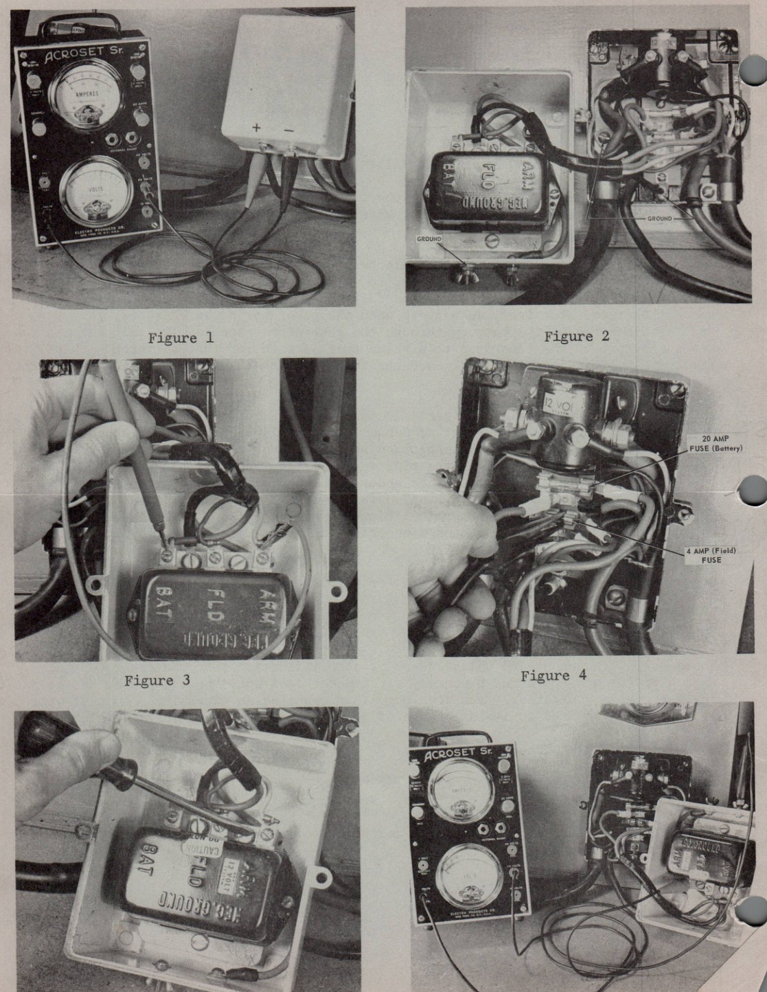
Disconnect all accessories from the power take-off terminals on the junction box and
connect the voltmeter to the terminals, See figure #1.
The accompanying charts show voltages and check points should any corrective measures
be necessary.
JOHNSON MOTORS
W. W. DeWees
Service Department
WWD:eb
NOTE: Post on your Miscellaneous index.
W. W. DeWees
- 3 - SB-783
| Readings | Indication | Check or Correction |
|---|
| Approximately 12.5 volts | Fully charged battery | OK - Proceed with tests. |
| Slightly below 12.5 volts | Partially discharged battery or bad connection in battery circuit. | Check wiring and connections. Fully charged battery may be installed to reduce checking time. |
| No reading | Open battery circuit. | Check 20 amp. fuse in junction box. Clean fuse clips - replace fuse if needed. (See Fig. 4) |
| Still no reading | Open battery circuit. | Check wiring and connections from battery to starter solenoid, at ammeter terminals and back to junction box. |
| Still no reading. | Open in ground side of battery circuit. | Check ground connections at battery and at two points in junction box and one in cover. (See Fig. 2) |
Start Engine and Operate at 3500 r.p.m. or above, approximately 3/4 throttle. If motor
is mounted on boat, suggest removal of propeller, install test propeller and operate
motor in gear to accomplish this.
| Readings | Indication | Check or Correction |
|---|
| Voltmeter reads above battery voltage, but not over 15.0 volts. Panel ammeter reads near 10 amps and decreases as voltage climbs. | Normal Operation. | After 15 minutes operation voltage should hold steady at 14.5 to 15.2 volts and ammeter reading should have fallen off to less than 10 amps. |
| Voltage above 15.2 volts Ammeter reading high. | Grounded field circuit or improperly operating regulator. | Disconnect field lead at regulator "FLD" terminal. Voltage should drop to 12.5 |
| If voltage drops to 12.5 with field lead disconnected at regulator. | Improperly operating regulator. | Regulator should be replaced or repaired by qualified electrical service station. |
| If voltage remains high with field lead disconnected at regulator. | Ground in generator field or field lead between generator and regulator. | Disconnect field lead at generator "F" terminal. |
| If voltage still remains high with field lead disconnected at generator. | Grounded generator field. | Refer generator to qualified electrical service station for repairs. |
- OVER -
SB-783 - 4 -
| Readings | Indication | Check or Correction |
|---|
| If voltage drops to 12.5 with field lead disconnected at generator | Ground in field lead between generator and regulator. | Locate ground and retape or replace lead. Reconnect lead to generator and regulator "FLD" terminals. |
| If voltmeter reading is correct and ammeter shows discharge. | Reversed terminal connections at ammeter. | *Be sure battery is installed for negative ground and reverse ammeter leads, if necessary. |
| If voltmeter remains at battery voltage and ammeter remains at zero. | No generator output. | Remove 4 amp. fuse, clean clips. Install new fuse & recheck. (See Fig. 4) CAUTION: Disconnect battery while removing or replacing fuse as any contact between fuse clips (field) and adjacent terminal (battery) will permanently damage regulator. |
| If voltmeter still remains at battery voltage and ammeter at zero. | No generator output. | Check wiring for correct hook-up and poor connections. Then carefully ground regulator "FLD" terminal to regulator base with screwdriver. (See Fig. 5) |
| If voltage climbs to a high value with "FLD" terminal grounded. Remove screwdriver immediately. | Inoperative regulator. (This operation by-passes voltage and current regulators.) | Regulator should be replaced or repaired by a qualified electrical service station. |
| If voltage remains low with field grounded. | Inoperative generator circuit breaker or defective wiring. | Move voltmeter lead (Fig. 1) from (+) take-off terminal to regulator "ARM" terminal. (See Fig. 6) Repair grounding as shown in Fig. 5. |
| If voltage now increases to a high value with field ground. | Inoperative circuit breaker in regulator. | Regulator should be replaced or repaired by a qualified electrical service station. |
* If the battery connections were incorrect and are changed, it will be necessary to
polarize the generator. To polarize, with a short piece of wire touch one end to the
regulator "ARM" terminal, then momentarily touch the other end to the regulator "BAT"
terminal. See Figure 3. CAUTION: Use extreme care that the center terminal (marked
"FLD" is not touched, as battery voltage applied to any point in the field circuit
will damage the regulator.