
November 7, 1960
Bulletin No. SB-808
Generators - d.c.
SUBJECT: GENERATOR INSTALLATION; 1961 V4S & V4SL-13 ENGINES.
When installing generators on 1961 V4S-13 engines it is important they be mounted so as
to provide maximum clearance between the terminals and the silencer cover in the lower
pan. When adapting generator kit (378050) to 1961 engines or when installing generator
kit (378346) be sure to check for proper mounting to preclude any chance of generator
failure.
FIGURE #1 shows the generator mounted as it has been done on V-4 engines thru the 1960
model. Notice the relative position of the armature terminal at the bottom of the
generator and the silencer cover. Under the thrust of the propeller the motor mounts
will allow the powerhead to move back. Under these circumstances it is possible for the
terminals to touch the silencer cover, or arc across to the cover, resulting in an elect-
rical failure.
FIGURE #2 shows the generator properly installed with the terminals behind the silencer.
This provides sufficient clearance so there is no danger of grounding the armature terminal.
The proper mounting of the generator is controlled by the location of the long thru-bolt in
the generator. This long bolt should be installed so that it is adjacent to the terminals
located at the bottom of the generator.
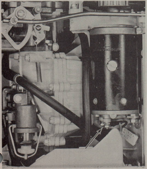
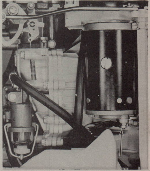
Figure 1
Figure 2
Generator terminals in front of high point
Generator terminals behind high point of silencer
of silencer. Wrong installation.
Correct installation. Refer to step two (2)
(over)
SB-808
- 2 -
Due to the close fit of the silencer cover and the generator, follow the instructions
listed below to reduce installation time.
1. Prepare engine in usual manner to the point where the generator is
ready to be mounted.
2. Check location of long generator thru-bolt. If it is not nearest
the terminals, switch the position of the long and short bolt.
3. Remove silencer cover and rear pad and plate.
4. Remove crankcase screw for generator-to-crankcase bracket.
5. Assemble the generator-to-crankcase bracket to the generator long
thru-bolt but do not tighten the nut at this time. If the bracket
interferes with terminal bushings, trim it to fit.
6. Assemble the Field and Armature leads to their respective terminals.
Leave the nuts loose at this time to allow wires to swivel.
7. Attach the generator to the mounting bracket.
8. Attach generator-to-crankcase bracket to the crankcase.
9. Route the Field and Armature wires correctly and tighten nuts.
10. Check Figure 2 for proper location of hoses. If hoses are not as
shown, change them to insure proper clearance.
11. Remove the rear pad plate from the silencer cover. Slide the cover
and pad into position over the air intake port. Place the two screws
in position and engage one or two turns.
12. Insert the pad plate into the silencer and push it down into position.
Lift the silencer cover and push the top of the pad plate until it is
in position behind the lips on the cover. Lower the silencer cover
with the plate still in position and tighten the screws.
13. Complete the assembly of the generator pulley, belt and the adjust-
ment of belt tension as shown in the instruction sheet.
JOHNSON MOTORS
W. W. DeWees
W. W. DeWees
Service Department
WWD:eb
NOTE: Post on your V4 index - 75 H.P.