
January 16, 1961
Bulletin No. SB-811
Crankshaft Groups
SUBJECT: Correct installation of connecting rods;
10 H.P. models QD-10 thru 22.
Since the factory discontinued supplying completely assembled piston and connecting rod
assemblies for the 10 h.p. engines, assembly of the detail parts must be performed by
the dealer.
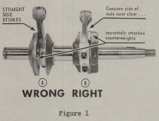
The critical installation is that of assembling the piston and rod correctly so that after
the rod has been installed on the crankshaft with the straight sides of the piston deflector
toward the intake port, the concave side of the rod will also face, and clear, the separate
counterweight which is attached to the inside of the main counterweight, figure 1, letter
'B'. Failure to correctly attach the rod to the crankpin as illustrated in figure 1-B will
result in the counterweight striking the beam of the rod as illustrated in figure 1-A. This
is the wrong installation and is to be avoided.
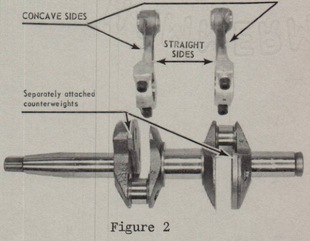
To insure correct installation of pistons and rods with the first attempt, be certain that:
1. The straight sides of the connecting rods face each other as illustrated in figure 2.
DO NOT ATTACH RODS TO CRANKPINS AT THIS POINT.
NOTE. This automatically locates the concave side of the rods toward the
heaviest side of the counterweights.
2. The pistons and rods are assembled so the straight sides of the piston deflectors
will be toward the intake ports after installing the piston and rod assemblies in
the cylinder. (Sloping sides of piston deflectors must be toward the exhaust ports).
3. The crankshaft is rotated by hand after the connecting rods have been installed on
the crankpins, but prior to installing the crankcase.
If care is exercised in following these three precautions, correct assembly of pistons and
rods, as well as correct installation on the crankshaft, should present no problem.
For additional information on this subject, refer to Service Manual #302231, page 164-7.
JOHNSON MOTORS
W. W. DeWees
W. W. DeWees
Service Department
WWD:eb
NOTE: Post on your QD-index 10 h.p.