Johnson Service Bulletin SB-813 - Alternator Equipped Engines
November 30, 1960. Factory guidance on the alternator-equipped Johnson 75 HP electrical system, including battery ignition, charging, junction box and tachometers.
November 30, 1960
Bulletin No. SB-813
Electrical System
SUBJECT: ALTERNATOR EQUIPPED ENGINES.
Introduction of the alternator equipped 75 H.P. engine brings with it some new factors
to be considered during installation, demonstration and servicing of Johnson outboard
engines.
The alternator in itself has proven to be quite trouble free and very versatile.
However, as with most of the new developments of today, although it is rugged, it is
also quite sensitive. It will not function properly, and may even fail, if carelessly
installed. Here is a brief outline of what you can expect from these new alternator
equipped engines and how to handle them for maximum trouble free operation.
1. IGNITION:
a. BATTERY: The ignition on these engines is battery operated, similar
to an automobile. Adhere to the battery recommendations which remain
the same as for our other electric starting engines.
b. IGNITION "ON" LIGHT: An ignition indicator light goes on when the
ignition switch is turned on. Mount this light in the dashboard so
it can be easily seen, even in sunlight.
c. COIL: There is a resistance wire (tagged) attached to the ignition
coil. This wire becomes very hot during engine operation. This is
normal. DO NOT SHORTEN, LENGTHEN, OR SUBSTITUTE THIS WIRE. Use only
a regular, service replacement resistance wire if required!
2. ALTERNATOR (a.c. generator)
a. OUTPUT: The alternator is an AC generator electronically controlled by
a transistorized regulator. It will provide approximately 5 amps
charging current at 500-600 r.p.m. It will provide a maximum of 20
amps at engine speeds over 2500 r.p.m. This output is over and above
the requirements for engine operation.
b. The alternator has the capacity to operate several electrical accessories.
(More sales for you of these electrical units.)
c. CURRENT DRAW (discharge): The current draw (discharge) of the alternator
with the ignition switch on and the engine not running is 4 to 5 amps
(registered on the ammeter). Under the same condition the ignition coil
will draw the same current. Therefore, with the breaker points open, the
current draw will be 5 amps; with the points closed it can go up to 10 amps.
This, of course, is with no other accessories on. You can see that if the
ignition switch is left on for a long period with the engine not running,
the battery can be run down. When the engine is running, the alternator
still requires about 5 amps while the coil requires only 1 amp or less.
d. SERVICING: When ever servicing an alternator unit, be sure to have the
complete electrical system available, if possible. This may mean either
service calls on the boat, or having the boat brought to your shop.
Testing procedures are being developed now. With proper equipment they
can be performed on the boat or in the shop.
WAUKEGAN, ILLINOIS
(over)
SB-813 page 2
3. ELECTRICAL CONNECTIONS: (very important)
a. The importance of good electrical connections cannot be overemphasized.
Anything that will create high resistance, such as loose screws and/or
corroded terminals, can cause trouble! This should be stressed in your
service shop and to the customer as preventive maintenance.
b. BATTERY CABLE CONNECTIONS: Reversed polarity (battery cable connections)
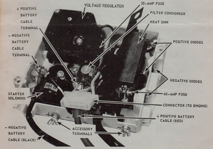
can cause immediate damage to the rectifier diodes. There are four diodes
and it is possible to burn all four if the polarity is reversed. These
diodes have a list price of $6.00 each. Damage due to reversed polarity
is readily recognizable by experienced personnel and is not considered a
failure due to defective parts or workmanship. Be very careful when
connecting the battery leads from the junction box to the battery. The
leads are tagged and the two terminals are of different sizes to assist
in preventing any error.
Continued on page 3
SB-813 Page 3
4. JUNCTION BOX:
a. VENTILATION & INSTALLATION: When operating at full output, the junction
box assembly gets very hot. It is important that the box be properly
mounted and adequately ventilated. The box must always be mounted upright
and within 15° from vertical. This provides the proper "chimney" effect
thru the box for adequate cooling. This is very important for extending
the life of the transistor in the regulator!
b. ACCESSORY CONNECTIONS: The ammeter and switch are calibrated into the
regulating circuit; therefore, all accessories have to be connected to
the accessory terminals on the junction box.
c. SERVICING: Always remove the battery leads before removing the junction
box cover. Do not make or break connections while engine is running.
Test procedures are being developed which may require operation of the
engine with the junction box cover off. This is the only time the battery
should be connected after the junction box cover is removed for inspection
or maintenance.
d. FUSE REPLACEMENTS: Be very careful when replacing fuses. Use only exact
replacements. When working with the 60 amp. fuse or any components attached
to it, be sure to replace everything in the correct sequence (see Parts Book)
to insure proper operation of the filter condenser. If the parts are in-
correctly replaced and the 60 amp. fuse blows, it is possible to damage
the rectifier diodes.
5. TACHOMETERS:
Tachometer leads are provided for operating a battery ignition type
tachometer. A magneto type tachometer will not work with this engine.
6. EMERGENCY STARTING:
a. DISCHARGED BATTERY: The engine has provisions for manual starting, using
an emergency rope starter. The voltage requirements for ignition is so
low that the engine can be easily started by hand even though the electric
starter motor will not even engage. If the switch has been left on for a
period of time and the starter will not operate, very often by turning the
ignition OFF and letting the battery recuperate for 15 or 30 minutes, hand
starting can be accomplished. CAUTION: There is no safety interlock when
hand starting. Be sure engine is in neutral!
7. TANK TESTING AND DEMONSTRATIONS:
Since the operation of these engines is dependent on the complete electrical
system, it is necessary to have a junction box assembly for tank testing and
boat demonstrations. You may find it most convenient to mount one unit on a
board so that it can be moved from tank to boat for testing or demonstration.
To summarize, the main source of trouble is slipshod, haphazard workmanship in the
initial installation. The alternator is rugged and efficient, has few moving parts
subject to wear, provides high output at low engine speeds, and allows the owner to
operate many more electrical accessories. Impress your customers with its few
peculiarities and the need for proper maintenance and you will find the alternator a
basically trouble free unit.