March 27, 1961
Bulletin No. SB-817
Transom Clamps
SUBJECT: Reinstatement of service on detail parts for transom clamps,
(with procedure for disassembly and reassembly).
75 h.p. model series V4S thru V4AL.
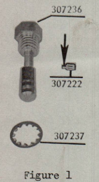
Figure 1 illustrates three detail parts of the transom clamps which
were originally serviced with introduction of the 1960 V-75 engine
but which were later discontinued. These parts have been reinstated
for service and are again available from your Parts Distributor at
the following list prices which are subject to the standard parts
discount.
PART NO. DESCRIPTION QTY. PER CLAMP UNIT PRICE
307222 Pin-Clamp 1 each $ .03
307236 Lockbolt-clamp 1 each 1.35
307237 Lockwasher 1 each .10
DISASSEMBLY:
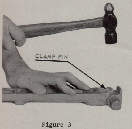
Figure 2 illustrates the initial step in removing the lockbolt from the
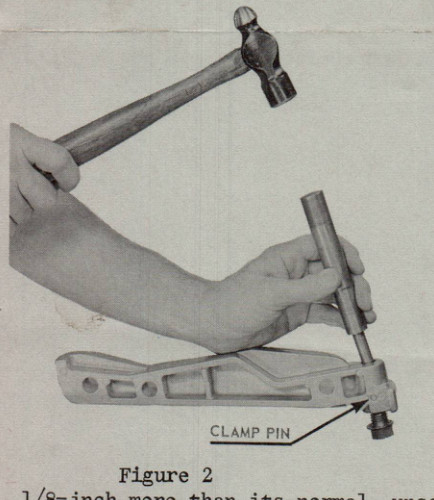
transom clamp. This step consists of just breaking
off the small end of clamp pin #307222 (arrow,
figure 1). Neither pound nor press the lockbolt all
the way out of the clamp! Doing so will cause the
piece of pin to wedge between the lockbolt and the
threads inside the clamp. As a result, continued
pounding will cause the piece of pin to cut a groove
in the threads which are thus damaged and rendered
useless.
To remove the lockbolt without thread damage:
1. Completely unscrew the lockbolt.
2. Securely place the clamp on a vise, or, if
available, in a corner of a workbench such as
is formed at the joint of bench surfaces and
endboards when used. Allow the lockbolt to
overhang as illustrated in figure 2.
3. Using a drift punch of proper diameter similar
to that illustrated (figure 2), shear the clamp
pin with one fairly solid blow of the hammer (two at most) to depress the lockbolt approximately
1/8-inch more than its normal, unscrewed position. This degree of depression is sufficient
to break the pin.
4. Turn the clamp upside down, jiggle the lockbolt to free the broken piece and remove the
lockbolt.
5. Using another drift punch with the appropriate diameter, remove the large end of the pin
from the transom clamp.
(over)