
January 15, 1961
Bulletin No. SB-827
Timing & Synchronization
Dist. & Carb.
SUBJECT: Timing and synchronizing;
75 H.P. alternator models V4A & V4AL-13 & 13C.
The design changes incorporated to convert the 75 H.P. engine from magneto to battery
ignition made relocation of some of the timing marks necessary. However, you will find
that the timing and synchronizing procedure is almost identical to that used on the
magneto equipped 75.
TIMING: to be sure the distributor is properly timed with the crankshaft, proceed as
follows:
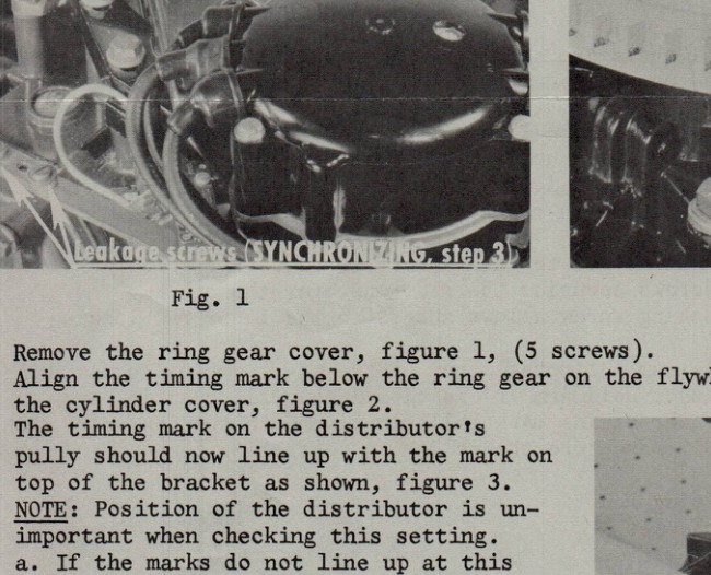
Fig. 1
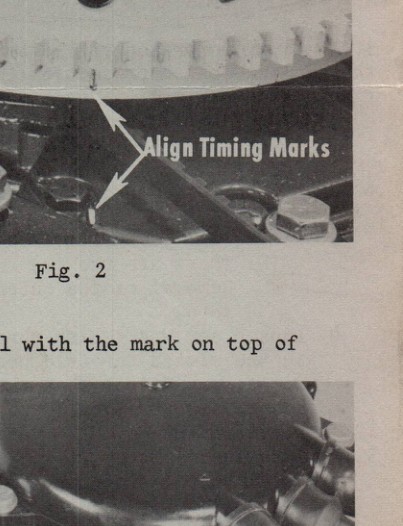
Fig. 2
1. Remove the ring gear cover, figure 1, (5 screws).
2. Align the timing mark below the ring gear on the flywheel with the mark on top of
the cylinder cover, figure 2.
3. The timing mark on the distributor's
pully should now line up with the mark on
top of the bracket as shown, figure 3.
NOTE: Position of the distributor is un-
important when checking this setting.
a. If the marks do not line up at this
point in the timing procedure, loosen
the distributor mounting bracket screws.
This should provide enough slack in the
belt so that the distributor pulley may
be rotated in order to properly line up
the timing marks.
b. Slide distributor mounting bracket out
to adjust belt tension and retighten
mounting bracket. Be sure not to let
pulley slip on belt while retightening
bracket.
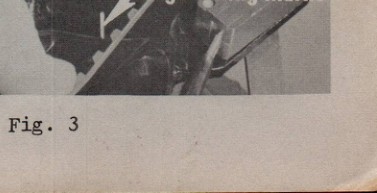
Fig. 3
WAUKEGAN, ILLINOIS
(over)
SB-827 Page 2
SYNCHRONIZING: To properly synchronize the carburetor with the distributor, proceed
as follows:
1. Place engine in forward gear.
2. Move the distributor to full advance position by hand.
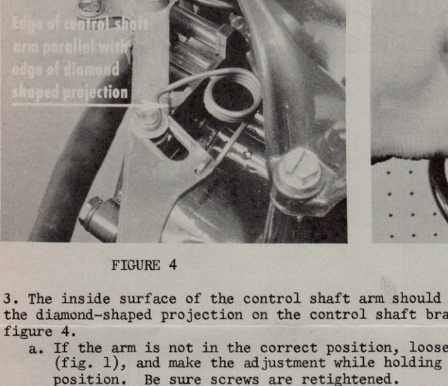
FIGURE 4
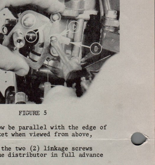
FIGURE 5
3. The inside surface of the control shaft arm should now be parallel with the edge of
the diamond-shaped projection on the control shaft bracket when viewed from above,
figure 4.
a. If the arm is not in the correct position, loosen the two (2) linkage screws
(fig. 1), and make the adjustment while holding the distributor in full advance
position. Be sure screws are retightened.
4. Check the position of the throttle arm with respect to the cam follower (figure 5,
letter 'A').
a. Remove the carburetor synchronizing rod to gain access to adjusting screw 'C'.
NOTE: There are two (2) set screws securing the rod, one over the other.
Removal of the outer locking screw allows access to the inner rod-locking
screw.
b. Loosen screw 'C'. With throttle cam 'A' rotated out of the way, arm 'D' should be
in the closed throttle position. Hold arm 'D' in closed throttle position and
rotate cam 'A' so that the synchronizing mark falls in line with the center of the
cam follower roller, figure 5. Make sure the roller is contacting the cam and
retighten screw 'C'.
5. Replace the carburetor synchronizing rod
through the pivot pin, leaving the set
screw loose. Advance the throttle lever
to full open position. Insert a .020 feeler
gage between the control shaft arm and the
full throttle stop on the cylinder casting
(Figure 6).
a. With the throttle fully advanced and
the gauge in position, fully open the
carburetor as shown in figure 6.
Tighten the synchronizing rod lock-
screw and replace the locking set screw.

FIG. 6
SB-827 Page 3
6. Remove the gauge and fully open the throttle (engine in forward gear). At
this point; (1) the throttle shaft arm should be fully against its stop on
the carburetor; (2) the throttle control shaft arm should be against its
stop; and (3) the distributor should be fully advanced against its stop.
NOTE: The .020 feeler gauge is used to compensate for any lost motion in
the linkage.
JOHNSON MOTORS

W. W. DeWees
Service Department
WWD:eb
NOTE: Post on your V4 index - 75 H.P.