Johnson Service Bulletin SB-832 - Alternator Charging Circuit
March 15, 1961. Factory troubleshooting procedure for the 75 H.P. alternator-equipped V4A and V4AL engines, including battery, regulator, rectifier, field winding and stator tests.
March 15, 1961
Bulletin No. SB-832
Alternator Charging circuit
SUBJECT: Trouble shooting the a.c. charging circuit;
75 H.P. alternator model series V4A & V4AL.
Most customer complaints on the a.c. generator will probably develop when the ammeter
does not indicate a charge while the engine is running, or when the battery fails to
retain a charge sufficient to consistently start the engine. If you receive complaints
of this nature, first check the battery's condition to be certain it is capable of
taking and holding a charge.
The importance of good electrical, as well as mechanical, connections throughout the
entire circuit cannot be overstressed. A large percentage of electrical system and
component failures are caused by one or more loose and/or dirty connections. ALWAYS
check electrical connections as your second step in any check of the charging system.
When trouble shooting the a.c. circuit, or any other electrical system, always
completely check the entire system. Often, obvious failures are merely the result of
other problems. A blown fuse, as one example, may have been caused by a short some-
where in the system.
If the test outlined on the following pages does not pinpoint the source of trouble,
it nevertheless serves to indicate the problem is probably a failure in the wiring.
Therefore, by making a continuity test of the circuit the point of failure can be
easily found.
A "dry run" through this test procedure is invaluable experience for the service
technician. By checking this test procedure against a new unit he will become
familiar with the system and also more readily learn what to expect of the various
tests when the charging system is functioning properly.
Make your checks carefully. Be particularly careful when shorting the regulator's
field terminal as instructed in paragraph III.B.2.(c).(1). An error at this point can
be costly! Check the basic alternator installation against earlier bulletin numbers
SB-813 and SB-831 which jointly list the precautions to be considered when installing,
running and servicing the alternator equipped engine.
TEST METER REQUIREMENT: The following outlined test procedure requires using the type
of multitester specifically called a Volt-Ohm-Milliammeter which in turn is more
commonly referred to as a "VOM". These VOM's can be obtained from local or national
electronic supply houses. CAUTION! Under no circumstances use a test meter with more
than a 12-volt source to check the rectifiers!
For the basic test procedures listed here, a laboratory type meter is not necessary.
However, when purchasing such a test instrument, along with other special tools, a
look into the future will be wise. A test instrument has been developed which will
more thoroughly check circuits on alternator equipped engines as well as past and
future electrical circuits. This instrument will be available in the very near future.
As soon as it is, a bulletin will be issued giving you the full particulars.
* * * * * *
(over)
SB-832 Page 2
TEST PROCEDURE
Since, as implied earlier, a check of the charging system is actually incomplete
unless the battery is also checked as a source of possible trouble, we urge that all
electrical system checks begin with the battery.
I. BATTERY CHECKS (See also Pp. 142-147 of V4 Service Manual):
A. VISUAL - look for:
1. Corrosion; 2. dirt; 3. frayed or broken cables; 4. cracked cases;
5. cracked cell covers; 6. loose hold-down clamps; 7. low electrolyte;
8. overfilling.
B. CHEMICAL & ELECTRICAL - check for:
1. Dead cells; 2. sulphated batteries; 3. voltage, etc.
II. ELECTRICAL CONNECTION CHECKS:
A. BATTERY CABLES: Do not overlook the possibility of reversed polarity! The
unit may have been previously serviced by someone who subsequently reversed
the battery cables which resulted in either a malfunctioning or inoperative
charging circuit.
B. Check all other connections for tightness and cleanliness.
If symptoms of malfunction or inoperativeness still remain at this point, proceed check-
ing the system further. From this point on your VOM tester becomes an indispensable
part of the test.
III. GENERATING SYSTEM CHECKS:
A. IGNITION SWITCH: Begin testing the circuit by turning the ignition switch to
the 'ON' position. The green 'ON' bulb should light, which indicates the
switch is conducting current.
1. Turn the switch ON and OFF a few times to further check the switch for
possible dead spots.
2. Current flow: With the switch in the 'ON' position and ALL ACCESSORIES
AND LIGHTS TURNED 'OFF', the ammeter should indicate a discharge of 4 to
10 amperes when current is properly flowing through the circuit. If no
discharge is indicated, the ammeter may be faulty. This, however, will
be determined later.
B. VOLTAGE & AMPERAGE CHECKS:
1. Engine idle (not running): Place the test meter (VOM) on a d.c. scale of
0 to 15 volts or higher.
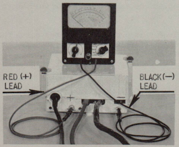
(a). Connect the VOM across the accessory terminals on the junction box,
figure 1. (Note polarity).
(b). With the ignition switch in the 'ON' position, the voltmeter should
now indicate battery voltage. (If no voltage is indicated, the 20
amp. accessory fuse is blown and must be replaced before continuing
the test.)
Figure 1
Figure 2
III. GENERATING SYSTEM CHECKS: (continued)
SB-832 Page 3
B. VOLTAGE & AMPERAGE CHECKS: (continued)
2. Engine running: With the voltmeter still connected across the accessory
terminals, start the engine and run it at a fast idle in neutral gear.
The voltmeter should now show a reading higher than battery voltage, and
the ammeter should show a rate of charge.
(a). If the voltmeter indicates an increased reading but the ammeter does
not, the ammeter is not working properly and should be replaced.
(b). If the voltmeter does not indicate an increased reading, the 60-amp.
generator fuse may be blown. To check, proceed as follows: (1) turn
off engine; (2) disconnect battery leads; (3) remove junction box cover;
(4) check 60-amp. fuse. If blown, replace.
(c). Reconnect battery cables (CAREFUL with polarity!), start engine and again
run at fast idle in neutral gear.
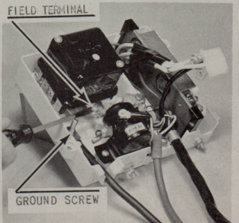
(1). While engine is running at fast idle, CAREFULLY ground the regulator's
field terminal to the ground screw in the junction box, figure 2.
(2). If both the voltmeter and ammeter show increased readings while the
field terminal is grounded, the regulator is defective and should be
replaced. (NOTE: The ammeter may show no change in the charging rate
which indicates it is not working properly.)
(3). If neither the voltmeter nor the ammeter show increased readings while
the field terminal is grounded, the regulator is operating sat-
isfactorily.
3. Turn off the engine and proceed checking further as follows.
C. RECTIFIER CHECKS (positive (+) & negative (-)): To check the rectifiers, place
your test meter in the ohms (resistance) position. This is basically a con-
tinuity test.
CAUTION! UNDER NO CIRCUMSTANCES USE A TEST METER OR INSTRUMENT WITH MORE
THAN A 12-VOLT SOURCE!
1. Disconnect the four rectifier leads.
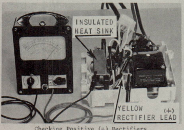
2. Positive (+) rectifier checks: Connect one test meter wire to the terminal
of one yellow rectifier lead, and the other meter wire to the insulated heat
sink, figure 3. Note the reading on the ohmmeter.
(a). Reverse the meter leads and again note the meter's reading.
(1). A high reading on one check and a low reading on the other indicates
the rectifier is good. However, a high reading on both checks, or a
low reading on both checks, indicates the rectifier is faulty and
must be replaced.
(b). Repeat the foregoing test for the other positive (+) rectifier.
Figure 3
Figure 4
Over
III. GENERATING SYSTEM CHECKS: (continued)
SB-832 Page 4
C. RECTIFIER CHECKS - (continued)
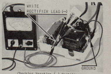
3. Negative (-) rectifier checks: Connect one test meter wire to the terminal
of one white rectifier lead and the other meter wire to ground, figure 4.
Note the meter's reading.
(a). Reverse the test leads and again note the meter's reading.
(1). Again, the same conditions apply for determining a good or faulty
negative rectifier as given in sub-paragraph 2.(a).(1) above for
the positive rectifiers.
(b). Repeat the test for the other negative (-) rectifier.
D. STATOR WINDING CHECKS: To check the field and stator windings, disconnect the
leads at the powerhead.
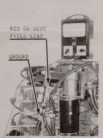
1. FIELD WINDING:
(a). Checking for grounded winding: With the meter still in the ohms
position, connect one meter wire to either the red or blue lead and
the other meter wire to ground, figure 5.
(1). An infinite reading (no continuity) indicates the field windings
are good. (Grounded windings are indicated by a reading less
than 5000 ohms.)
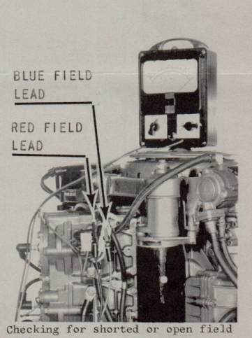
(b). Checking for shorted or open winding: Connect the test meter between
the red and blue leads, figure 6.
(1). A reading between 1.69 and 3.14 ohms indicates the windings are
good. (A lower reading indicates the windings are shorted, while
a considerably higher reading indicates the windings are open.)
Figure 5
Figure 6
III. GENERATING SYSTEM CHECKS: (continued)
SB-832 Page 5
D. STATOR WINDING CHECKS: (continued)
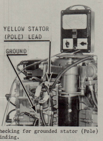
2. STATOR (pole) WINDING:
(a). Checking for grounded winding: Connect one test meter wire to either
yellow lead, and the other meter wire to ground, figure 7.
(1). An infinite reading (no continuity) indicates the windings are good.
(A reading less than 5,000 ohms indicates the windings are grounded.)
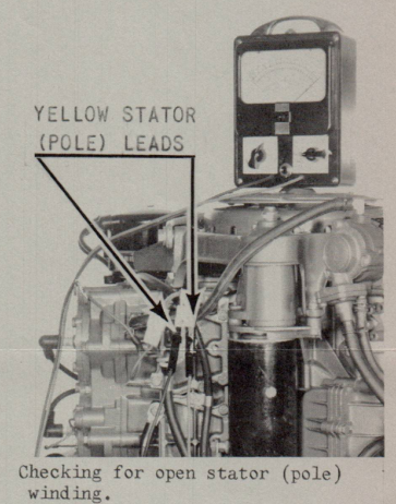
(b). Checking for open winding: Connect the test meter between the yellow
stator leads, figure 8.
(1). A reading less than 1 ohm indicates the windings are good. (An
infinite reading (no continuity) indicates the windings are open.)