
SUBJECT: Mounting 40 h.p. Electramatic engines.
Examination of the 40 h.p. electric shift gearcase will reveal it to be considerably longer in the fore and aft dimension than gearcases of standard shift RD's. This greater length correspondingly increases "side area" which causes the Electramatic gearcase to resist lateral (side to side) change more than the standard gearcase when going into sharp turns. If the engine is mounted without the special clamp, figures 2 and 3, this resistance to lateral change causes the engine to twist on the transom. Left turns cause the engine to revolve about the right clampscrew while the left screw simultaneously slips higher on the transom. Right turns cause the opposite reaction.
To prevent this, the 1962 - 40 h.p. Electramatic engines include a modified transom plate, part #378955, and a special transom clamp as standard equipment. Both pieces are packed with the engine, and must be installed on the transom as part of the engine installation.
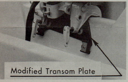
FIG. 1 - Modified Transom Plate
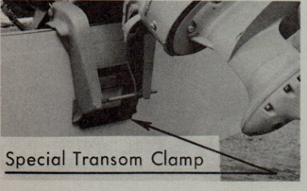
FIG. 2 - Special Transom Clamp
FOLLOWING IS THE MOUNTING PROCEDURE.
- Place engine in its correct running location on the transom. Do not tighten clampscrews.
- Slip transom plate between the clampscrews and the transom. Center the transom plate and tighten clampscrews securely to properly index transom plate on the transom. Mark its location with a pencil and remove engine from the boat.
- Mount the transom plate in the conventional manner using the four (4) screws provided.
- Replace engine on the boat and tighten the clampscrews, figure 1. Be certain the engine is fully and firmly seated on top of the transom to avoid mislocation of the clamp in step seven (7).
- Tilt engine to the trailing position.
- Place the special transom clamp in position at the bottom of, and between the engine's stern brackets, figure 2.
- Hold clamp in this position and drill two 5/16 inch holes in transom. Best results are obtained by using a high speed drill bit.
- Be certain installation is water tight. Use a good waterproof caulking compound as a sealer between the clamp and transom.
- Mount clamp in place by installing the two bolts, followed by the washers inboard of the transom, and then the nuts. These parts are supplied with the clamp.
SB-878
Page 2
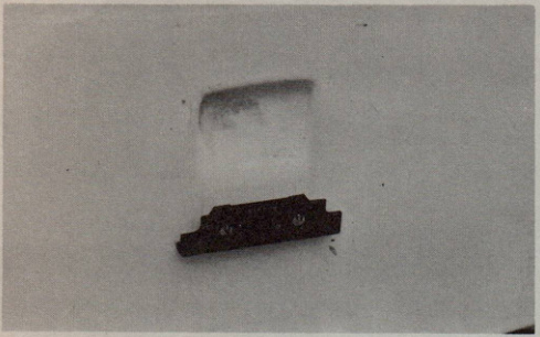
FIG. 3
Figure 3 illustrates the special transom clamp mounted on the boat. The engine can be removed and again remounted without further disturbing the clamp.
The components making up the kit included with the Electramatic engines may also be used on standard 40 h.p. engines, if desired, to provide more positive anchorage. Order these parts from your Parts Distributor.
The list of parts involved is as follows:
| Quantity | Part No. | Description | List Price |
|---|---|---|---|
| 1 | 378955 | Transom plate | $2.00 each * |
| 4 | 306193 | Screw - transom plate | .10 each ** |
| 2 | 309190 | Bolt - transom clamp | .20 each ** |
| 2 | 309191 | Nut | .15 each ** |
| 2 | 309192 | Washer | .03 each ** |
| 1 | 309193 | Special transom clamp | .65 each ** |
The list prices quoted are subject to discounts as follows:
*378955 - standard accessory discounts.
** All other parts - standard parts discounts.
Service Department
WWD:eb
NOTE: Post on your RK index.