Johnson Service Bulletin #910 - Remote Control Cables
Issued June 13, 1962, this two-page bulletin addresses remote control cable clamp placement on Electramatic engines. Johnson identified improper clamp positions as a cause of hard throttle operation, abrupt shifting, restricted steering, and electric starter problems. The original illustrations show the specified 36-inch forward and 37-inch aft cable arrangements.
June 13, 1962Bulletin No. SB-910 Remote Control Cables
SUBJECT: Locating first and last remote control cable clamps- ELECTRAMATIC engines.
Field reports indicate many dealers are experiencing problems with (1) ELECTRAMATIC engines slamming in and out of gear, (2) hard-to-operate control box throttle levers, and/or (3) electric starters not energizing. In checking into the causes of these problems, it was found that our installation instructions had not been followed, and two important steps were overlooked. Both steps are contained on page 5 of the Installation Instructions under the procedure entitled "ATTACHING REMOTE CONTROL CABLE TO BOAT". They are:
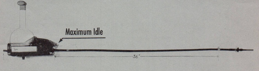
Location of the FIRST cable clamp 36 inches behind the control box with the red auxiliary (idle) lever fully advanced as illustrated in figure 1. (This is also illustrated in figure 8, page 5, of the instructions.) On some boats, however, the 36-inch location may fall in an undersirable area, as between ribs, etc. In such instances it is permissible to locate the clamp on the nearest rib PROVIDED the location is not less than 33 inches nor more than 42 inches from the control box. If a satisfactory mounting surface is not available within this variation, one must be provided by installing a strip, or stringer, across the ribs. Failure to adhere to the variation can cause the engine to idle at an excessively high rpm which results in slamming in and out of gear.
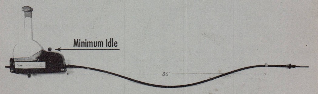
FIG. 1FIG. 2
over
SB-910 Page 2
The instructions, page 5, also refer to providing 1½ inches of cable slack. Disregard this specification and concentrate only on locating the first clamp as instructed in the preceding paragraph. Then, with the auxiliary lever retracted to minimum idle position, the necessary slack will be obtained automatically, figure 2. Keep in mind that cable slack will vary as location of the first clamp varies.
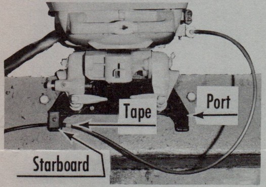
Location of the LAST cable clamp at the stern must be at least 37 inches from the end of the brass ferrule nearest the knurled adjusting nut. Failure to maintain this minimum length can result in cable kinking, hard throttle operation and restricted steering. To simplify locating this clamp, the 37-inch point on our cables is marked with colored, plastic tape. This tape must be placed beneath the clamp, or between the clamp and the attaching point on the engine. NEVER place the clamp between the tape and the end of the cable! These requirements apply whether the cable is clamped directly to the boat or to a transom plate, figure 3.
FIG. 3FIG. 4
The 40 h.p. RK series engines include a transom plate which has both port and starboard brackets for properly clamping remote control cables. It is necessary to secure cables to only one bracket. When the control box is mounted on the starboard side, the starboard bracket only is used, and serves as the final clamp. Port side installation of control boxes requires the cable be clamped in the port bracket. Figure 4 illustrates that 37 inches of free cable permits unrestricted steering, as well as freedom from cable kinking and sharp bends.
For those cables in the field which are not marked with tape, the 37-inch dimension is specified and illustrated in each of the assembly figures contained on pages 8 through 11 of the Installation Instructions. These figures illustrate suggested routing and anchoring points of cables for (1) port and starboard installation of control boxes, (2) single and twin engine installations with and without transom plates, and (3) for boats with and without dry wells.
The problem of electric starters not energizing is the result of advancing the red auxiliary throttle lever to its maximum idle position. This position actuates the safety switch which in turn prevents starting at too high a throttle setting. This information is part of the operating instructions found on the outside back cover of the instruction manual.