Johnson Service Bulletin SB-913 - Electramatic Gearcase Disassembly and Assembly
Issued August 13, 1962, this six-page factory service bulletin describes the electric-clutch gearcases on Johnson 40 HP RK(L)-24 and 75 HP V4A(L)-14 engines. It covers shifting circuits, cable routing, removal, gear and clutch spring disassembly, bearing cleanliness, and reassembly. Figures 1 through 11 are reproduced with the procedures they illustrate.
Factory instructions are presented for historical reference. Confirm applicability and specifications before performing repairs.

Gearcases - ELECTRAMATIC
August 13, 1962
SUBJECT: Disassembly & assembly of ELECTRAMATIC gearcases.
40 h.p. RK(L)-24 series
75 h.p. V4A(L)-14 series.
GENERAL:
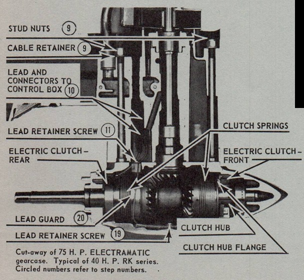
The ELECTRAMATIC gearcases on the subject engines generally function in a manner similar to the familiar mechanical arrangement except gear engagement is accomplished electrically, through a switch and electromagnetic coils (electric clutches), instead of by mechanical linkages. In both cases, while the engine is running, the forward and reverse gears freely revolve in opposite directions on the propeller shaft until one gear or the other is engaged. In the ELECTRAMATICS, the gears have a helically wound steel spring (clutch spring) locked to them. As long as the gears are not coupled to the propeller shaft, the clutch spring is free to revolve about the clutch hub.
When the remote control lever is moved forward it actuates an electric switch in the control box which closes the circuit (green wire) to the forward electromagnetic coil (electric clutch) in the gearcase. The instant the electric clutch is energized electromagnetism attracts and anchors the free end of the clutch spring to the flange of the clutch hub. With both ends of the clutch spring thus securely anchored, the revolving gear causes the spring to wrap around the hub which creates a direct coupling with the propeller shaft. It is readily seen that motive power is chronologically transmitted through the pinion gear, forward gear, clutch spring, clutch hub, propeller shaft and finally the propeller.
Forward drive is thus retained until the remote control lever is returned to neutral position which automatically breaks the circuit to the forward electric clutch. The clutch instantly de-energizes and releases the clutch spring. The spring then resumes its normal, retracted position, and is again free to revolve about the clutch hub. This restores the engine to neutral. Shifting into reverse causes an identical action.
SERVICING:
Current drawn by each electric clutch when energized is 1.7 amperes ± .2 amp. Servicing the ELECTRAMATIC gearcase is similar to servicing their mechanical counterparts with the following important exceptions:
A. ELECTRIC SHIFTING CIRCUITS:
Care must be exercised in removing or installing the electrical wiring (blue and green) to prevent loosening of connectors and cutting insulation. Any insulation break between the gearcase and the junction box, or between the junction box and switch in the remote control box, can cause one of the following two malfunctions:
- If the insulation is broken on both wires at the same point in the shifting circuit and both bare wires come in direct con-
B. B. CLEANLINESS is of prime importance in assembly!
The running clearance between the clutch hub and the bronze bearing in the front gear assembly is only .0003" to .0015". Any foreign matter such as grit, metal particles or other dirt trapped here will cause premature and excessive wear! Because of these close tolerances, assembly of the bronze bearing on the clutch hub, and in turn this subassembly into the gear and clutch spring, must also be made with care! Careless assembly of these parts in both operations can create burrs on the bronze bearing, the slightest of which can result in faulty gearcase performance and, again, excessive wear.
DISASSEMBLY (for addition or removal of extension kits or for other servicing):
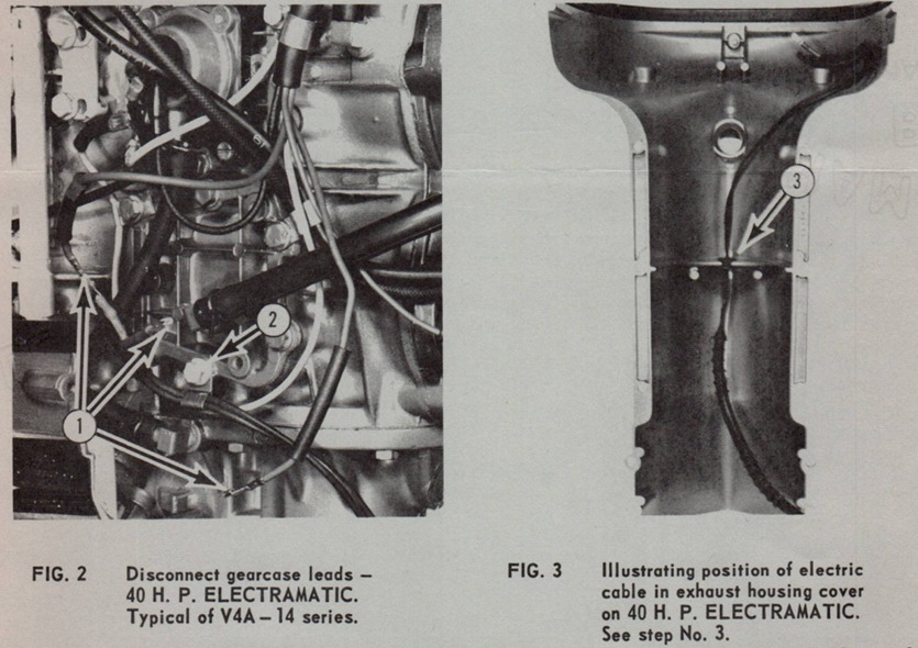
- At the back of the powerhead, slide black connector insulation on the blue and green wires and disconnect, figure 2.
- Loosen clamp holding wires to powerhead, figure 2.
- On 40 h.p. models only, remove rear exhaust housing cover. Note the recess in the inner flange of the cover for the cable grommet, figure 3. Remove grommet from cable.
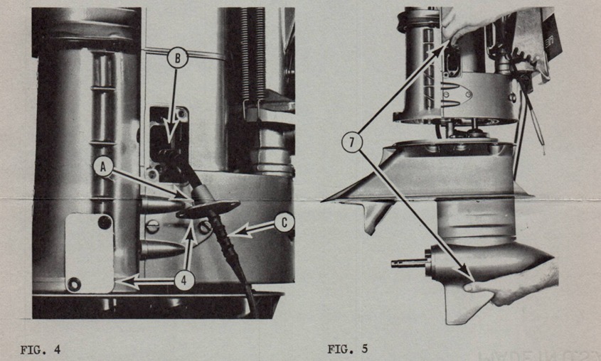
- On 40 and 75 h.p. models, remove cover plate from front exhaust housing cover. Loosen the exhaust housing plate, figure 4. (Both are better known as the shift rod connector inspection plates on mechanically shifted engines.)
- Remove exhaust housing plate from the cable, figure 4, arrow A. (ASSEMBLY NOTE: Lubricate spools lightly to ease assembly.)
- Remove gearcase-to-exhaust housing screws. (To avoid cutting insulation on electric cable and broken or loose connectors, do not allow gearcase to drop freely.)
- While supporting gearcase with one hand, carefully feed cable through opening in exhaust housing with the other, figure 5.
- Add or remove gearcase extension kit in conventional manner if gearcase was removed for that purpose, and reassemble in reverse order using same electric cable. (Note the two (2) sets of spools or ridges. The bottom set is for standard length engines, figure 4, arrow "B", the upper set for long shaft, figure 4, arrow "C".)
If gearcase removal was necessitated for servicing the component parts continue disassembly in the following order:
- Loosen upper gearcase from lower by removing stud nuts, figure 1. (Allow cable retainer to remain on rear stud. It cannot be removed until upper and lower gearcases are separated.)
- Lay gearcase horizontally on bench and separate upper gearcase from lower only as much as necessary to disconnect electric wires. Slip rubber insulators back and disconnect knife connectors, figure 1. Remove upper gearcase.
(ASSEMBLY NOTES: (a) Place cable retainer on cable before assembling upper gearcase to lower. It cannot be installed afterward.
(b) IMPORTANT If the lower pinion bearing is the free-roller Hyatt unit, the rollers will fall out of the bearing race when the pinion gear is removed with the lower gearcase! Be certain there are a total of 20 rollers prior to reassembly and that NONE remain in the lower gearcase! Use needle bearing assembly grease #378642 liberally in the bearing race (see SB-909) to hold the rollers in place while the pinion gear is reassembled through the bearing.)
(c). Carefully fold electric wires into pocket of upper gearcase to prevent pinching wires and cutting insulation, figure 1.
- Remove retainer screw holding blue and green leads, figure 1.
- Remove gearcase head and bearing assembly using flywheel puller #378103 and adapter kit #378104.
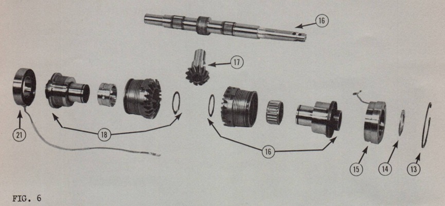
- Remove tru-arc retaining ring, figure 6.
- Remove thrust washer figure 6. (ASSEMBLY NOTE: Locate bronze side of washer toward the electric clutch.)
- Screw two (2) of the gearcase head screws into opposite sides of the rear electric clutch and carefully rock it out. Feed clutch wire (blue) down through opening.
- Remove rear gear, clutch spring, clutch hub and roller bearing assembly by withdrawing the propeller shaft. (See step #25A for further disassembly of this subassembly.)
- Remove pinion gear, thrust bearing and thrust washer. (ASSEMBLY NOTE: Thrust washer must be located on top of the flat, roller thrust bearing to provide a running surface for the rollers.)
- Remove front gear, clutch spring, clutch hub and bronze bearing assembly. (See step #25A for further disassembly of this subassembly.)
- Remove screw and washer holding protective tubing for front clutch lead (green) in bottom of gearcase, figure 1.
- Remove guard for lead from front coil, figure 1. (ASSEMBLY NOTE: When replacing guard, be certain that the front clutch lead is definitely in the guard’s channel, i.e., between the guard and the wall of the gearcase.)
- Remove front electric clutch, figure 6. (ASSEMBLY NOTE: This clutch is a mild press fit and must be carefully aligned so the root of the lead will slip into the recess located in the bottom of the gearcase for this purpose.)
DISASSEMBLY AND ASSEMBLY NOTE FOR STEPS 21, 22 & 23:
Special tools have been developed for disassembly and assembly of these three steps. You will be notified by Service Bulletin as soon as these become available.
- Remove front bearing.
- Remove bearing race.
- Reassemble gearcase in reverse order.
25. GEAR, CLUTCH SPRING, HUB & BEARING SUBASSEMBLIES:
DISASSEMBLY:
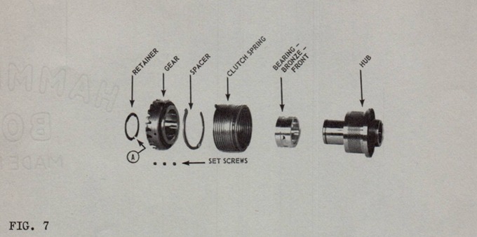
- Remove tru-arc retainer, figure 7.
- Slide gear and clutch spring off of hub and remove bearings. NOTE: The front gear assembly contains a bronze bearing while the rear contains a free-roller bearing (22 rollers).
- Loosen set screws in gear.
ASSEMBLY:
Cleanliness is of prime importance.
Refer to "B" under SERVICING.
- Clean set screws, gears, spacers and clutch springs with degreasing solvent and allow to dry.
- Start set screws (3 per gear) into gears one or two turns.
- Assemble spacer and clutch spring into gears in position and sequence illustrated, figure 8.
- Apply Loctite sealant, grade "D", sparingly to threads of each screw. One drop is the maximum. Avoid entry into moving parts. (See SB-911.)
- Torque screws 15-20 inch pounds, figure 9.
- Allow gear and clutch springs to stand for several hours at normal room temperature (about 70°F.) prior to assembling bearings and clutch hub. For those who have oven facilities, hardening time can be reduced to ten (10) minutes by baking at 200° to 225°F.
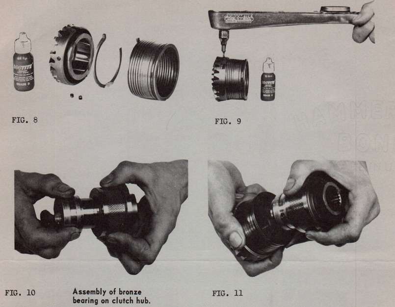
- Dip bronze bearing and clutch hub (front gear set) into OMC type "C" gearcase lubricant. CAREFULLY align and assemble bearing on the hub, figure 10.
In the event the bronze bearing becomes cocked on the hub, DO NOT FORCE assembly by wringing or tapping!
Refer to "B" under SERVICING.
- Dip gear and clutch spring assembly (front gear set) into Type "C" lubricant. CAREFULLY repeat alignment and assembly of hub and gear similar to step "J", figure 11.
- Install tru-arc retainer.
- Reassemble gearcase in reverse order of disassembly beginning with step 24, page 4.
W. W. DeWees
Service Department
WWD:eb
NOTE: Post on your RK and V-75 indexes.