to Wiring Harness.
40 and 75 H.P. ELECTRAMATIC Engines.
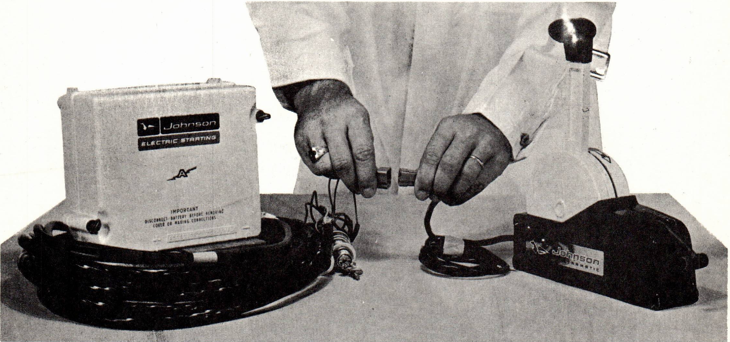
We have received reports indicating that the nylon connectors which attach the remote control box shift lead to the switch plate wiring harness (Figure 1) occasionally come uncoupled in use. When this occurs the shift mechanism is completely inoperative.
These two connectors have a built in lock device designed to prevent their uncoupling in use. The pressure required to properly lock the two connectors is, however, more than might normally be expected. Further - if the lock device is not properly engaged it works against itself and actually forces the connectors apart.
Proceed to couple these connectors by pressing them firmly together until a definite 'snap' is heard. This 'snap' indicates that the lock device has engaged to secure the connection.
Familiarize yourself with these connectors by coupling and uncoupling them several times prior to your next ELECTRAMATIC installation.
Robert Compton
Service Department
NOTE: Post on your RK-40 H.P. and V75 indexes.