October 25, 1962
Bulletin No. 925
Special tools
SUBJECT: Installer set - for 40 and 75 h.p. Electro-Magnet and front
bearing race installation.
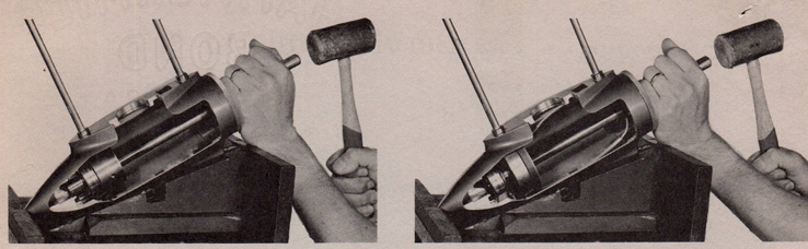
The group of special tools illustrated here are designed to install the front
propeller shaft bearing race and the front Electro-Magnet on 40 and 75 h.p.
electric shift engines. Since there is no one part number covering the complete set,
each item will in turn have to be ordered
individually - order blank enclosed.
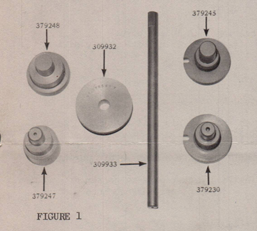
All of the illustrated drive heads (379230,
379245, 379247, 379248) can be used with
the common drivershaft, part #309933, and
guide plate, part #309932, to accommodate
race or Electro-Magnet installation.
These special tools are all presently
available from Outboard Marine Corporation
Parts Depot at the following net prices
C.O.D. orders are not accepted. Mail all
orders with prepayments to:
OUTBOARD MARINE CORPORATION PARTS DEPOT
P.O. Box 470
GALESBURG, ILLINOIS
DO NOT ORDER THESE TOOLS FROM JOHNSON MOTORS
OR FROM YOUR PARTS DISTRIBUTOR.
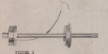
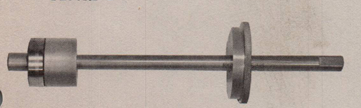
FIGURE 3
PART NO. DESCRIPTION NET PRICE
309932 Guide plate $ 1.90
309933 Driver shaft .75
379248 Bearing race installer
(75 h.p.) 2.30
379247 Bearing race installer
(40 h.p.) 2.30
379245 Electro-Magnet installer
(75 h.p.) 3.90
379230 Electro-Magnet installer
(40 h.p.) 3.90
BEARING RACE INSTALLATION
1. Select appropriate driver head.
2. Secure driver head to driver shaft with
allen screw.
3. Position bearing race on driver head,
holding driver and race in upright
position.