
Johnson Service Bulletin SB-930 - Modified Carburetor Linkage

January 10, 1962. Factory instructions for the modified throttle linkage on 10 H.P. QD-23A and later engines, including carburetor and magneto synchronization.

Johnson Motors Service Bulletin letterhead
January 10, 1962
Bulletin No. SB-930
SUBJECT: Modified Carburetor Linkage - 10 h.p.
Models QD-23A and up.

Carburetor linkage on 10 h.p. engines has been slightly modified, starting with model QD-23, which necessitates making an adjustment for full throttle opening whenever the carburetor, or linkage, is removed and replaced on these engines. Model QD-23A linkage modifications are identified on the carburetor illustrated in figure 1, by arrows A, B, C and D.
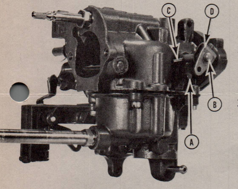
Figure 1, modified carburetor with labeled linkage changes A through D
FIGURE 1.

A- Boss added to carburetor body.

B- Machined flat removed from end of throttle shaft.

C- Roll pin replaces cotter pin.

D- New throttle shaft arm.

Engines prior to model QD-23A had corresponding machined flats on the throttle shaft and throttle shaft arm. The flats were aligned during assembly and no adjustment was required.

The modified throttle shaft and new throttle shaft arm do not have these machined alignment flats and, require adjustment after they are assembled. Adjustment would naturally have to be made upon reassembly if the linkage had been disassembled in removing the carburetor for repairs, or, if someone has unknowingly loosened the throttle shaft arm set screw and accidentally changed the setting. The correct procedure for this adjustment and subsequent steps for synchronizing carburetor and magneto is explained as follows.

The performance and dependability which have been engineered into these engines are dependent on proper adjustments. Don't try to rush the following adjustments, and don't settle for an adjustment that is 'close'. Thoroughness and exactness are keys to top performance when synchronizing carburetor and magneto.
(over)
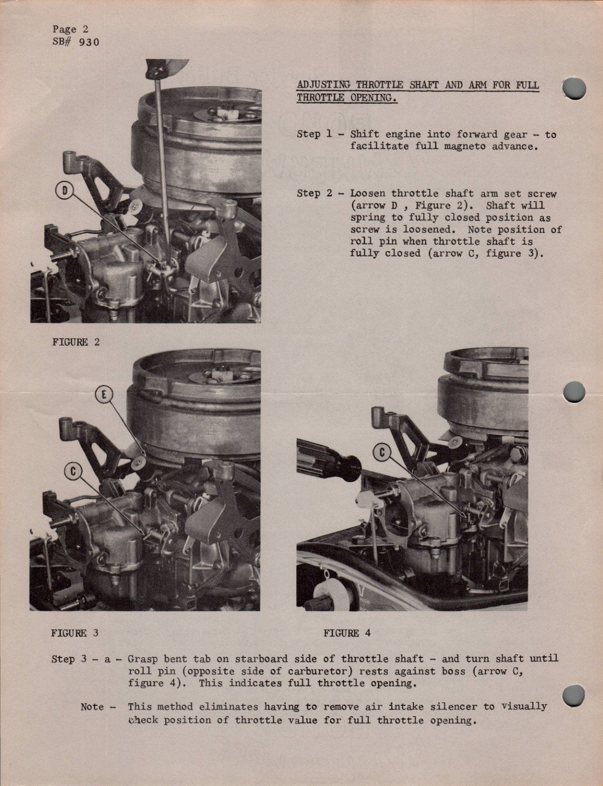
Original factory page 2 showing carburetor adjustment steps and photographs
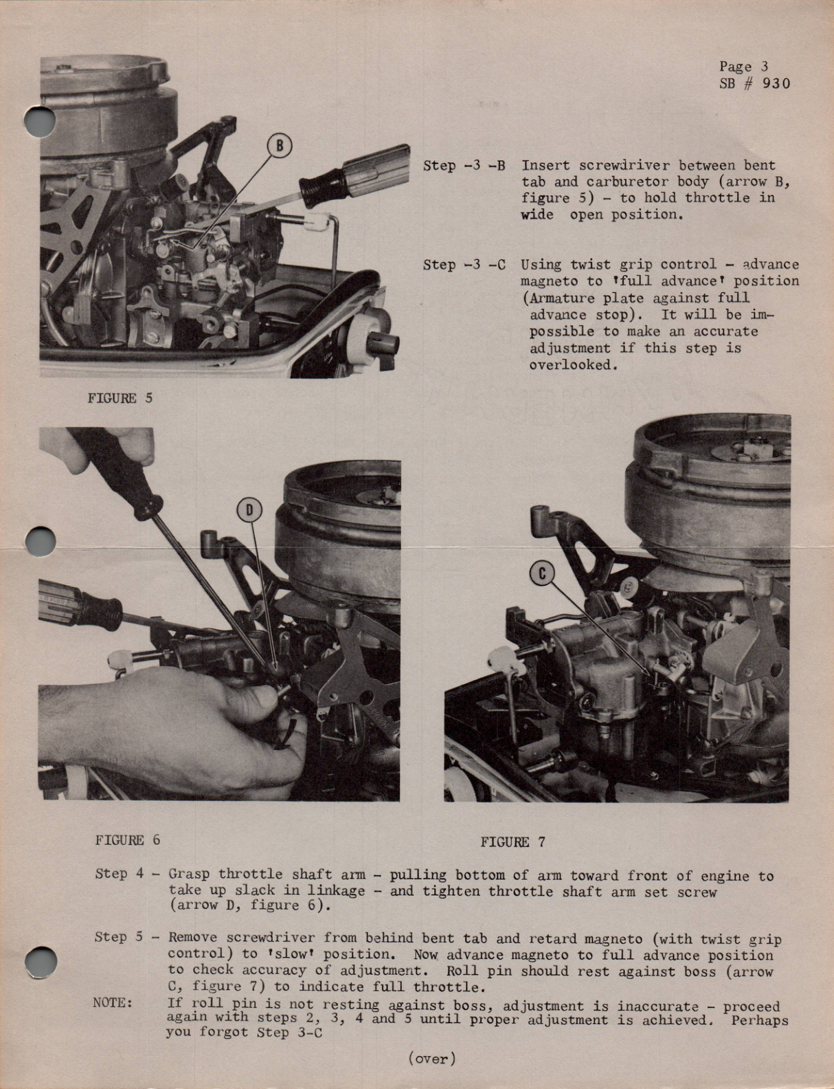
Original factory page 3 showing carburetor adjustment steps and photographs
Page 4
SB # 930

SYNCHRONIZE CARBURETOR AND MAGNETO

Step 1- With motor in forward gear retard magneto (using twist grip control) to 'slow' position.

Step 2- Slowly advance magneto while watching throttle shaft - to point where first opening of throttle shaft is noticed. Index mark on magneto cam should be in alignment with center of cam roller (arrow E, Figure 3) - the moment throttle shaft starts to open. If this alignment is not exact, adjustment is necessary - proceed as follows.

Step 3- A - Loosen retaining screw under leading end of magneto cam. Hole in leading end of cam is elongated for adjustment - push cam in as far as possible.

B - Align index mark with exact center of cam roller - (arrow E, Figure 3).

C - Insert screw driver behind leading end of cam to move cam toward roller. Again - watch throttle shaft while adjusting cam out. The moment throttle plate starts to open adjustment should stop. Hold cam in this position and tighten retaining screw under cam.

Step 4 - Repeat steps 1 and 2 to check this adjustment. It must be accurate. If not, repeat step 3 until proper adjustment is achieved.

Sincerely,

JOHNSON MOTORS

Robert Compton
Service Department

RC:eb

NOTE: Post on your 10 h.p. index.

Document notes

Pages 2 and 3 are retained as high-resolution images to preserve the exact factory photographs, callouts, and step positioning. Pages 1 and 4 contain selectable HTML text.