February 22, 1963
Bulletin No. SB-943
Electrical System
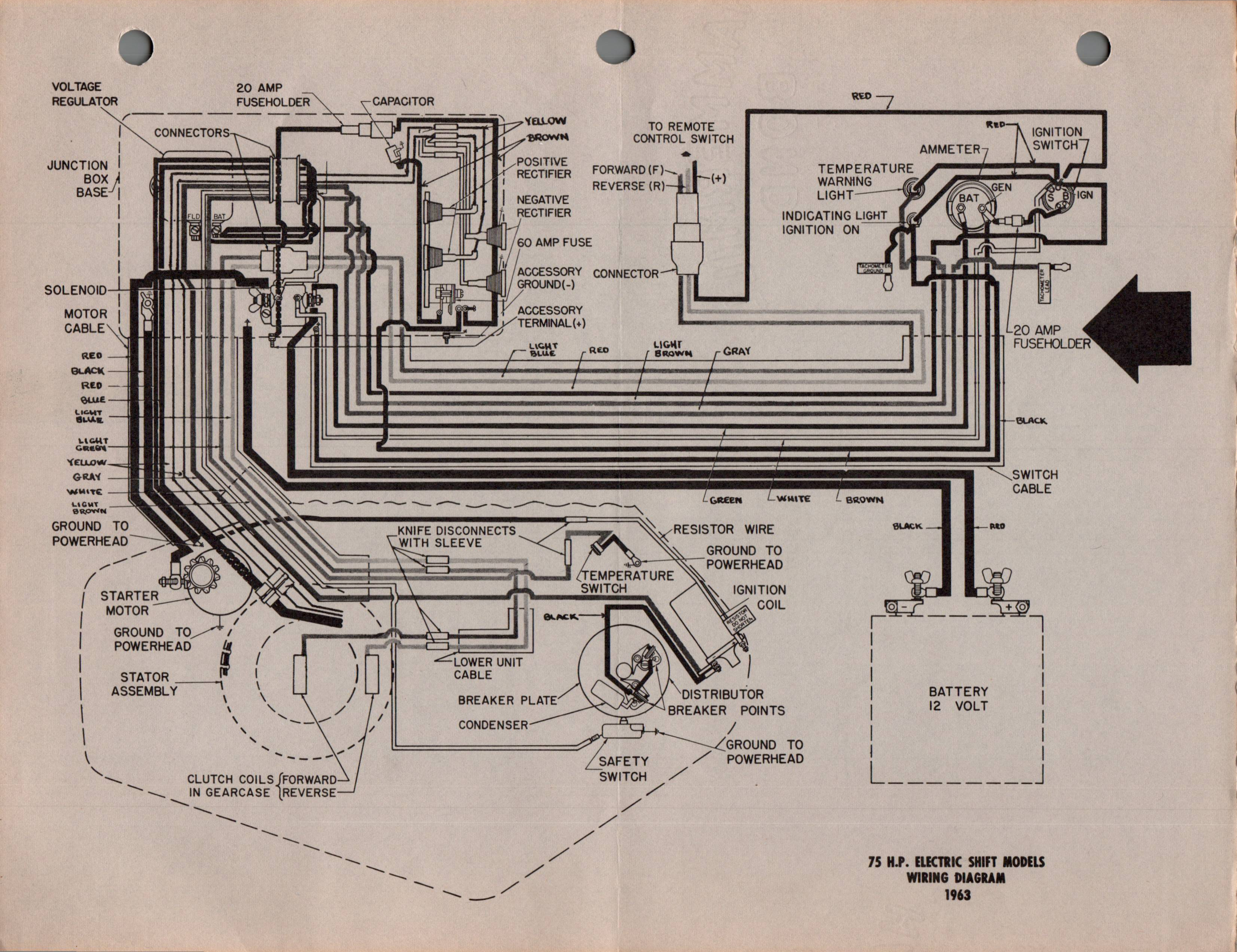
SUBJECT: 1963 75 H.P. WIRING DIAGRAM - MODELS V4A, V4AL-15
IMPORTANT
(20 Amp Fuse Added)
A 20 amp fuse was recently incorporated in the wiring harness on 1963
model V4A, V4AL-15 engines. It is connected between the generator
terminal on the ammeter and the battery terminal of the key switch.
See wiring diagram (arrow) on back side of this bulletin.
The fuse has been added to protect the wiring from overloads, however,
if it should blow, due to an overloaded or shorted circuit, all engine
electrical circuits, including the ignition circuit, become inoperative
until it is replaced.
Since information concerning the fuse and its location has not been
included in all 1963 model V4A, V4AL-15 Owner's Manuals, we suggest
you inform owners of its location, also that carrying a spare fuse
would be advisable. Always check this fuse first if the ignition
"on" indicator fails to light with the key in the "on" position or
the starter does not operate.
The electrical systems on other 1963 models remain unchanged and 1962
wiring diagrams should be used for reference.
JOHNSON MOTORS
Robert Compton
Service Department
RC:eb
NOTE: Post on your model V-75 (75 h.p.) index.