SB-# 961
Carburetion
June 20, 1963
SUBJECT: RUBBER TIPPED CARBURETOR FLOAT VALVE.
Rubber tipped carburetor float valves are now being used on all production engines -
see illustration, figure 1.
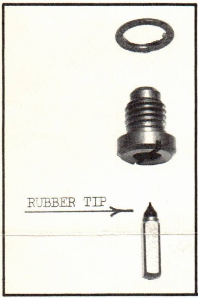
The rubber tip on the new carburetor float valve
acts to cushion the wearing action of valve and
seat. Thus, valve life is increased, seat wear
is not noticeable and carburetor flooding due
to valve malfunction is greatly reduced.
The following engines use the indicated rubber tipped float valve assemblies:
JW-10 thru 17S
V4-10 thru 11B
V4S-10 and up Use assembly #379312
V4A-13 and up
CD-10 and up
AD-10 thru 12
QD-15 and up Use assembly #379313
FD-10 and up
FDE-10 thru 12
JW-18R and up
RX-10C and up
RD-10 and up
RDE-16 thru 19C Use assembly #378895
RDS-20 and up
RK-24 and up
QD-10 thru 14A Steel needle only -
Use assembly #375654
List prices of the new carburetor float valve assemblies are as follows:
378895 - $1.35
379312 - $1.35
379313 - $1.35
Your standard parts discount applies - order only from your Parts Distributor.
over
Page 2
PROPER FLOAT LEVEL ADJUSTMENT:
When installing a new carburetor float valve assembly, it is extremely important
that float level be checked and accurately adjusted as described here. If the float
level is too high, fuel will start flowing through the high speed nozzle prematurely,
delivering more fuel to the engine for a given running condition than it should
(RICH MIXTURE). On the other hand, if the float level is too low, fuel will start
flowing through the high speed nozzle later than it should and will in this instance
deliver less than the required amount of fuel for a given running condition (LEAN
MIXTURE).
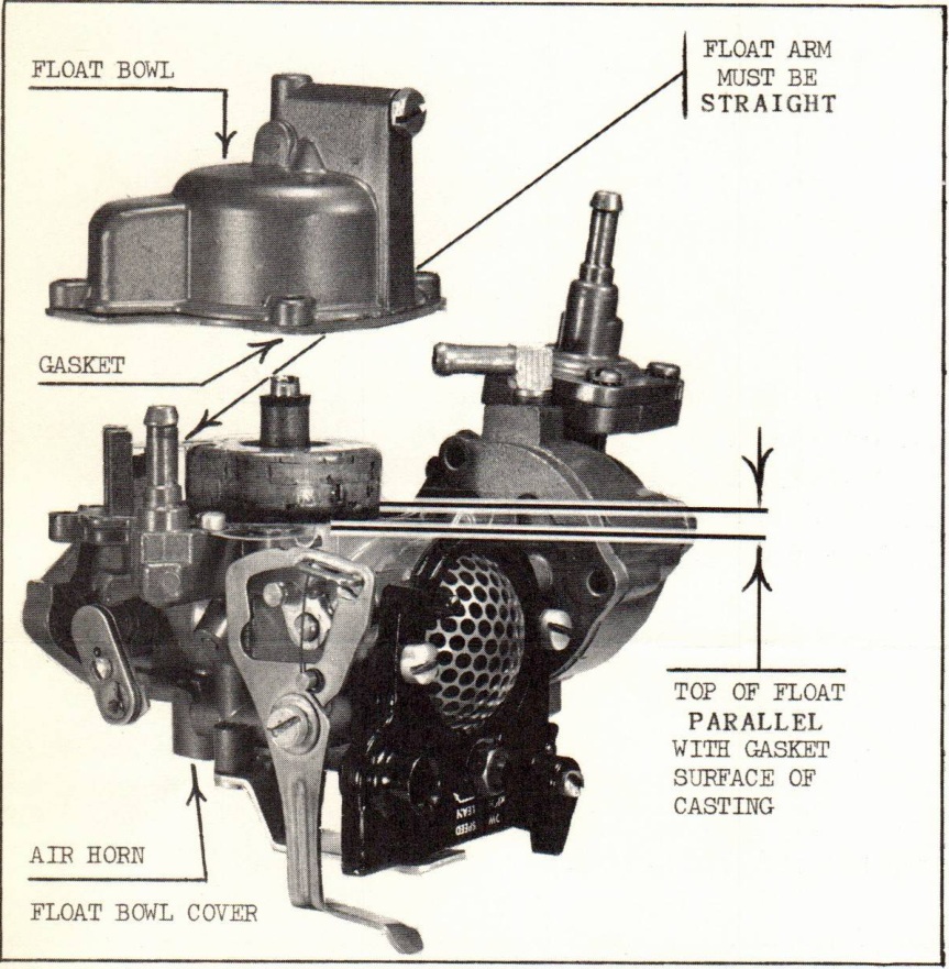
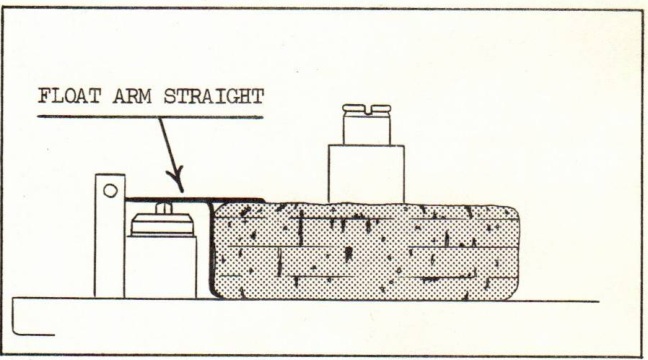
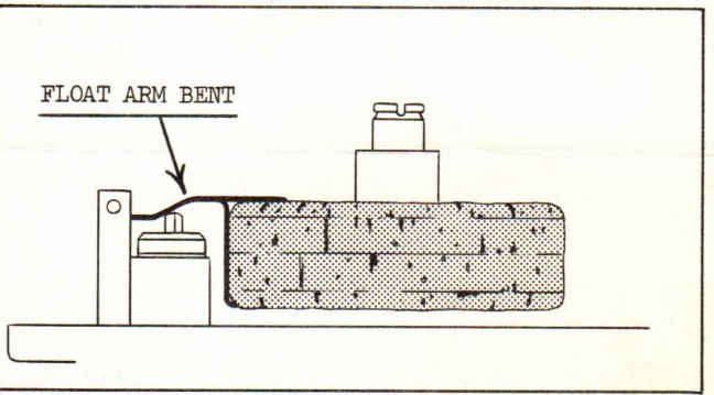
Figure 2
Figure 3 - Proper Adjustment
Figure 4 - Improper Adjustment
Carburetor floats for all engines listed on the preceding page (except QD-10 thru 14A)
are adjusted with the carburetor air horn (float bowl cover) in an inverted position,
so that the float is parallel with the gasket surface of the casting - see figure 2.
The float arm must also be straight as indicated in figure 3. In event that float arm
is bent or twisted, as shown in figure 4, inaccurate fuel level will result.
To adjust the float on QD-10 thru 14A carburetors - proceed as follows. Remove and
invert the float bowl. Top of float will be parallel to gasket surface of float bowl
casting if float adjustment is correct. To adjust float height, bend small tang at end
of float arm that slips over groove in check valve needle.
Always install a new float bowl gasket after checking the float level and stress
cleanliness during all carburetor work.
Sincerely,
JOHNSON MOTORS
R. Compton
Administrative Assistant
RC:eb
NOTE: Post on all indexes.