August 15, 1963
SUBJECT: Screened Vent Holes in the Ignition Distributor
APPLIES TO ENGINES: All V-4 Series - Both Magneto and Battery Ignition Systems.
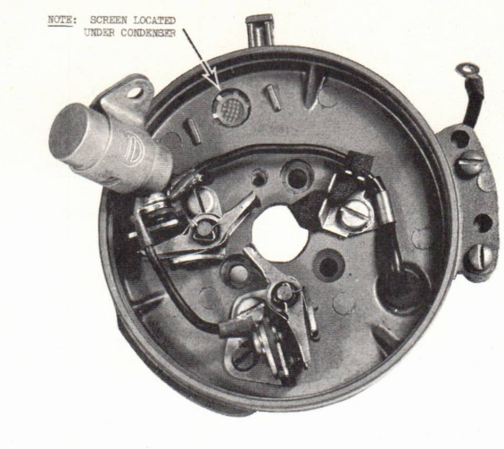
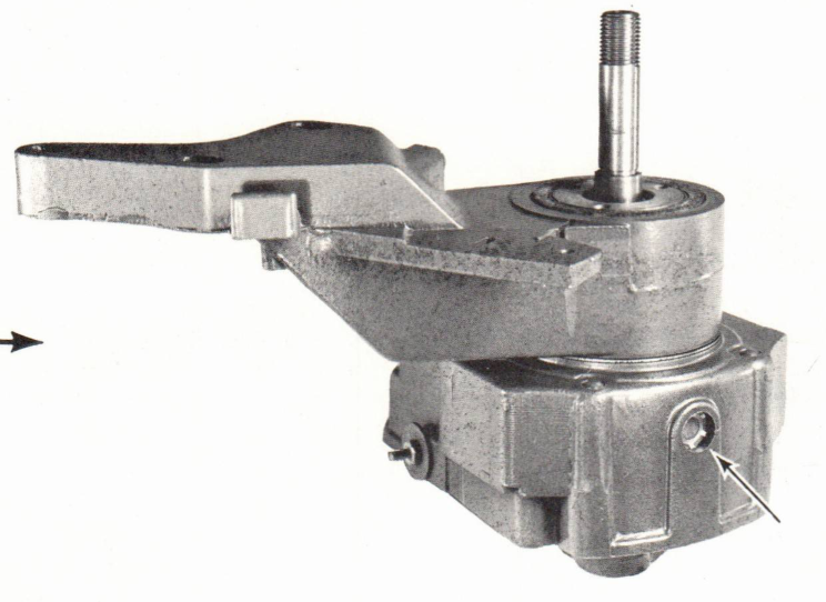
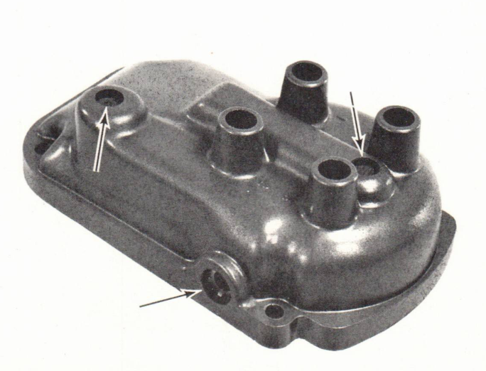
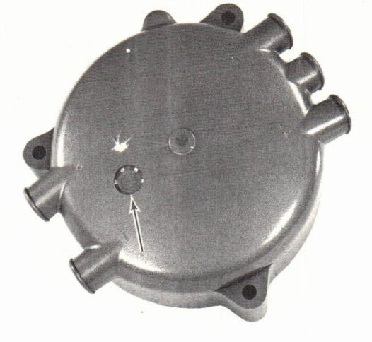
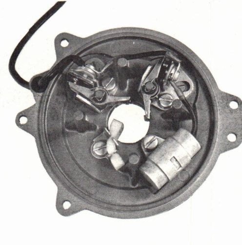
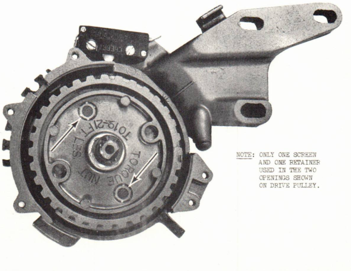
Screened vent holes will be found in various locations on all V4 series Magneto or Battery Ignition distributors. See figures 1 and 2, on pages 2 and 3.
These vent holes are employed to dissipate ozone and moisture from inside the distributor to the atmosphere. Ozone is a corrosive form of oxygen and the direct result of an electrical arc. Moisture, in this instance, results from humidity and cycles of hot and cold temperature. Both ozone and moisture in the distributor contribute to electrical failure by oxidizing metallic components of the ignition system. Moisture may also create "stray" electrical sparks inside the distributor to cause erratic firing.
Screens have been added to these vent holes to keep water or foreign matter from entering the distributor, and, to prevent gasoline fumes from being ignited by electrical spark from within the distributor. As flame or spark cannot pass through the fine mesh of these vent screens, any stray spark from the ignition system is therefore safely contained within the distributor.
Since these screens are installed by the factory for a specific purpose, no attempt should be made to run the engine with one of them missing. We recommend that routine inspection of all vent screens be made whenever a V4 series engine comes into the shop for service. Screens that are clogged by dirt and oil residue must be cleaned for adequate ventilation. Screens that have been punctured or are missing must be replaced immediately. Use the following parts when replacing distributor vent screens on either Magneto or Battery Ignition systems (except Battery Ignition drive pulley - which uses only one screen and one retainer in each opening).
Install in this order: screen - spacer - screen - retainer. Note that the retainer is dished slightly - and must be installed with the contour of its gripping segments facing out.
All screws in the distributor assembly should also be checked for tightness during ignition work. Loose screws are apt to work out exposing an open (unprotected) hole in the distributor. Likewise, missing screws must be replaced before any attempt is made to start the engine.
Robert Compton