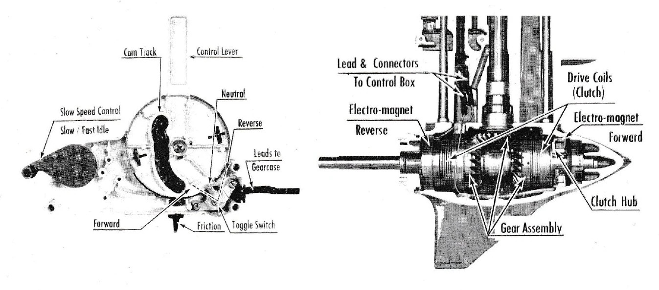
The Electramatic gear shift assembly consists of: « 1. The pinion - attached to the driveshaft. 2. The forward driving gear. 3. The reverse driving gear. 4. The propeller shaft. 5. The clutch hubs - keyed to the propeller shaft. 6. The clutch drive coils each anchored respectively to the forward and reverse driving gears and as such both assemblies float on the clutch hub (keyed to the propeller shaft). 7. The two electro magnets are energized by battery current. A lead from each is directed to a toggle switch in the control box and appropriately attached to the forward and reverse sides.
When shifting to forward, the toggle actuated by the control lever, establishes the forward driving circuit - the energized electro-Magnet then attracts and anchors the free end of the clutch drive coil to the clutch hub. In so doing, the revolving coil is caused to drag and subsequently wrap itself Tightly around the hub to create a direct coupling with the propeller shaft. It may be easily seen now that the path of energy applied to drive the propeller is thru the pinion, forward driving gear, clutch drive coil, clutch hub, propeller shaft and, of course, finally the propeller, Forward drive is thus retained until the control lever is returned to neutral position at which time the circuit is automatically broken. The electro magnet instantaneously de-energizes. The clutch coil resumes its normal position to release its grasp on the clutch hub. The assembly now floats on the clutch hub and neutral is restored. Like action occurs in reverse. See operators manual.
Current drawn by each Electro-magnet when activated is 1.7 AMP.
 Jack Penland