 SPB #352January 20, 1964
SUBJECT: PROCEDURE FOR PREPARING SHOP LAY-OUT PLANS.
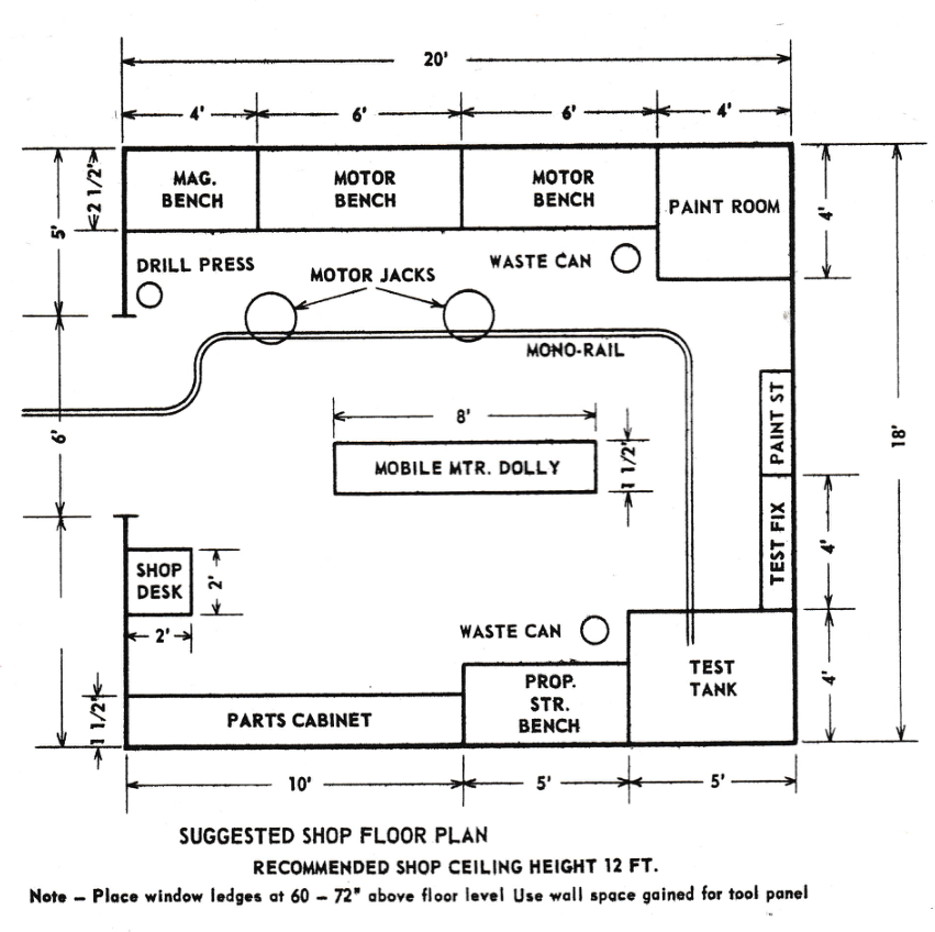
It's along about that time of year when you may possibly be thinking of plans for next year's activity - expand to cope with the rapidly growing Johnson family and future prospects. Perhaps your shop is a bit too small or not arranged for efficient operation - good enough for an earlier day but outmoded for 'to-day'.
Undoubtedly, many of you will want to consider building, remodeling, moving into larger quarters or simply reorganizing the present shop lay-out for a better and more efficient service operation - making everything as convenient and accessible as possible to reduce operating costs - reduce the "time" per job.
It's not always possible to lay out the shop as you'd eventually like it while building or remodeling is in progress which, often results in doing 'the best you can' upon completion of the program - usually in a hurry and to your regret later on when the season opens up. Things (tools, equipment, etc.) aren't quite placed where they might have been for best service performance. You find now that the benches are in the wrong place, the drill press or grinder ought to have been set over 'against the other wall', the test tank is not conveniently reached, etc. Here's where a bit of pre-planning enters - (early enough), just after ascertaining how much floor space is to
Page 2-
be allotted the shop, actual shape of the area, placement of doors, windows, etc. How do you do it - here are some suggestions.
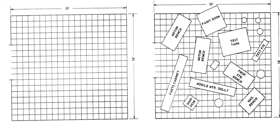
1. First lay out the assigned shop area on a sheet of paper (wrapping paper will do) - scaled one-half inch to the foot, indicating door and window locations. Longer, high (off the floor) windows make for more usable wall space - don't overlook when building or remodeling. "Cross-line" the lay-out vertically and horizontally, spaced 1/2 (one-half) inch apart - scale equal to one foot on the intended shop floor plan as shown here.
2. Make "cut-outs" (scaled also 1/2" to the foot) for all pieces of equipment you'll probably want to install. Cut out accordingly. Make as many bench cut-outs as benches planned for. It's possible that some of your friends may lift an eyebrow when observing shears and paper in hand - but - assure them there's nothing out of order, you've just got a job to do - to help him (the owner) get his motor "fixed" better and quicker in the future.

Courtesy - Kinn Motors Marine: Oconomowoc, Wis.
Page 3
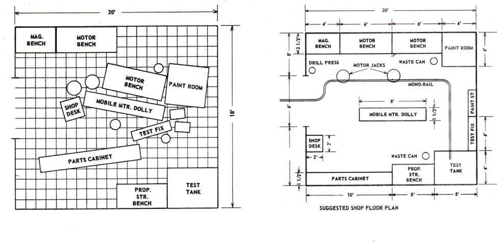
3. Then start placing the cut-outs on the cross-lined floor plan - the benches where you think they ought to be, magneto repairs, the test tank, motor rack, etc., located for greatest accessibility. Make several arrangements in this manner. Select the one which appears to be most suitable and practical for the allotted floor space.
4. "Tack (cut-outs)" in selected positions with adhesive. Ruled cross lines will assist in determining dimensions for simplification later on during actual process of the final lay-out as well as to facilitate determining distance between benches, desks, test tank, etc. at a glance.
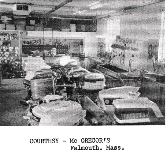
Mono Rail Systems may be ordered through the following: (Keep ceiling high enough for Mono Rails - at least 12 ft)
Cleveland Fram Rail
Div. of Cleveland Crane & Engrg. Co.
7280 East 289th Street
Wickliffe, Ohio
American Mono Rail Co.
13115 Alkers Avenue
Cleveland 7, Ohio
Lowden Machinery Co.
2502 West Avenue
Fairfield, Iowa
Richards-Wilcox Mfg. Co.
500 - 3rd Street
Aurora, Illinois
COURTESY - Mc GREGOR'S, Falmouth, Mass.
Page 4
Obviously there will be about as many different sized dimensions and differently shaped floor plans as there are those of you who plan to build, remodel or move into larger quarters. It doesn't matter a great deal actually, simply adhere basically to steps of procedure 1, 2, 3 and 4. You can plan better this way and be all ready with planning when it comes time to 'move in'.
In the event of building - starting from "scratch", don't neglect window placement. It's important, of course, to be properly "lighted" but so often window placement robs you of too much valuable wall space - wall space which otherwise might be used for tool panels. Every effort should be made to panel the tools for ready access - set the windows high enough.
Place window ledges at 60 - 72" above floor level. Use wall space gained for tool panel.
With the larger V-4 model motors, you'll surely want to plan for a Mono-rail system so don't overlook ceiling height and ceiling support.
Recommended ceiling height for the shop (if you're setting up a new building) is 10' 6" (12' if you can make it) to accommodate the larger tank, the V-4's, the mono-rail and electric hoist. Lesser ceiling height may require some tilting of the V-4's when performing the tank installation. Over all length of a V-4 is approximately 57" - from tip of skeg to tip of the lifting loop.
Discuss this phase of building plans with the architect - fluorescent lighting, too.
Include in your own plans, the larger test tank for the V-4's - in this case, allow an area of 5 ft. long (front) by 4 ft. wide. When planning for the larger tank, don't fail to consider a service shop door wide enough to accept it.
Keep right on planning for the future with JOHNSON.
Obtain power hoists from the following:
Manning, Maxwell & Moore, Inc.
Broadway at Park Avenue
Muskegon, Michigan
Chisholm - Moore Hoist Corporation
6050 Fremont Avenue
Tonawanda, New York
Lowden Machinery Co.
2502 West Avenue
Fairfield, Iowa
Robbins and Meyers - Hoist & Crane Div.
Springfield, Ohio
Yale & Towne Mfg. Co.
Roosevelt Blvd.
Philadelphia, Pennsylvania
P.S. Don't overlook planning for a boat "rigging" Department.
JOHNSON MOTORS
 Jack Penland
Service Promotion Manager
JP:eb