
ELECTRIC TROLLING OUTBOARD - 9.9 THRU 135 HP MODELS
On installations that require longer battery cables, we recommend the following procedure:
Cut off approximately two feet of cable on each battery lead (two feet on red and two feet on black), then splice (see chart below) into each cable the desired length extension. Splices should be staggered (not side by side).
| ENGINE | 4' EXTENSION | 10' EXTENSION | 18' EXTENSION |
|---|---|---|---|
| Electric Outboard | 6' of #10 GA | 12' of #8 GA | 20' of #6 GA |
| 9.9 & 15 H.P. | 6' of #8 GA | 12' of #6 GA | 20' of #4 GA |
| 25 & 40 H.P. | 6' of #6 GA | 12' of #3 GA | 20' of #1 GA |
| 50 H.P. | 6' of #4 GA | 12' of #2 GA | 20' of #1 GA |
| 70 to 135 H.P. | 6' of #3 GA | 12' of #1 GA | 20' of #0 GA |
Cable splices should be kept up out of bilge to prevent laying in water.
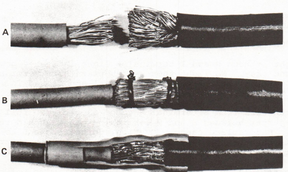
To splice cable, remove approximately one inch of insulation on each cable. Spread stranded cable (Figure A) open on each cable (Caution: wire is sharp - handle with care), then insert smaller cable into larger cable. Squeeze stranded wire with pliers. Then wrap stranded wire with a small wire (Figure B) and twist with pliers to make compact splice. Apply liberal amount of solder flux (DO NOT USE ACID FLUX) and solder. Remove small wire wrapped around splice, slide heat shrink tube over splice and shrink with suitable heat source (Figure C).
Service Department