ACCESSORIES #1198
August, 1978
August, 1978
SUBJECT: INTEGRAL TILT AND TRIM STUCK IN TILTED POSITION
Under certain conditions the integral tilt and trim unit may become stuck in the full tilt up position. Although the motor can be moved down to the trim range by opening the manual release valve and motored back up again after the manual release valve has been closed, it will still be hydraulically locked in the tilt up position.
CAUSE:
If the motor is stored and/or trailered in the full tilt up position with the trim rods extended, a change in temperature from low to high will cause the oil in the trim cylinders to expand, resulting in increased pressure between the tilt trim separation valve and the trim check valve. If this pressure exceeds the “pop off” pressure of the trim down pump relief check valve then the pump pressure will open the trim down relief valve before it opens the trim check valve, routing all of the pumped oil back to the reservoir.
PREVENTION:
To prevent a hydraulic lock from occurring, follow these procedures whenever trailering or storing the motor in the tilted position:
a. Tilt motor up and set trail lock.
b. Tilt motor down against trail lock and continue to tilt down until the trim rods are fully retracted.
PROCEDURE FOR UNLOCKING:
Use the following procedure for correcting
a hydraulic lock:
1. Tilt the motor all of the way up and
set the trail lock.
2. Open the manual release valve one
turn.
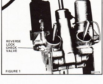
3. Remove the Reverse Lock Check
Valve. See Figure 1.
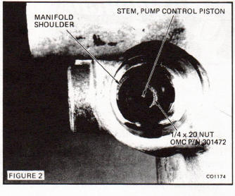
4. Place a 1/4 x 20 OMC P/N 301472
nut over the stem of the pump con-
trol piston making sure that the
nut is inside of the shoulder in the
manifold. See Figure 2.
5. Replace and torque the Reverse
Lock Check Valve to 50-60 in. lbs.
(5.5 - 7.0 N·m). As the check valve
is tightened against the nut, the nut
will force the pump control piston
to open the trim check valve.
6. Remove the check valve and 1/4 x
20 nut.