
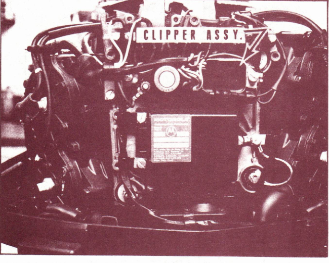
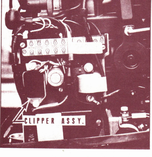
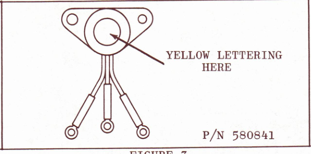
We recently made a change in production to add a safety device to the ignition circuit. The purpose of this device, called a clipper circuit, is to protect the C.D. ignition system against an open or intermittent battery circuit. Addition of the clipper circuit required a new rectifier assembly. This new rectifier can be identified by the yellow lettering on the rectifier and a smaller mounting hole. Earlier rectifiers have black or red colored lettering. See Figure 3.
NOTE: This rectifier is not interchangeable with earlier ones and must be used on engines with a clipper circuit. Engines which have the clipper circuit can be identified by the suffix "D" in the model number. Early 1970 engines had the suffix "B".
Neither the service manual nor the 1970 C.D. troubleshooting
booklet covers the test procedures for this new feature. Refer to this bulletin when testing the clipper circuit.
b. An inoperative C.D. pulse pack and an open or intermittent battery circuit.
c. A blown fuse and replacement fuses continue to blow.
a. Make sure shift diode assembly is good by testing per service manual instructions.
d. If meter reading is very high or infinite, the test lead connected to the purple/green diode lead will be the case lead.
Now that you have determined which ohmmeter lead is the case lead, test the clipper assembly following Steps 2 through 5.
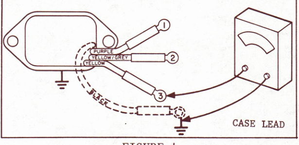
IMPORTANT: Early production clipper assemblies were manufactured with three leads. Latest clipper assemblies have a fourth lead (black) for ground. Connect ohmmeter case lead to black lead on four lead clippers.
Step 2 -
a. Momentarily short the purple clipper lead to case of clipper circuit.
b. Release purple lead and connect Ohmmeter as shown in Figure 4.
c. If meter pointer does not move, proceed to Step 3.
d. If meter reads less than 300 ohms, replace clipper.
Step 3 -
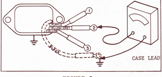
a. Momentarily short the purple clipper lead to case of clipper circuit.
b. Release purple lead and connect Ohmmeter as shown in Figure 5.
c. If meter pointer does not move, proceed to Step 4.
d. If meter reads less than 300 ohms, replace clipper.
Step 4 -
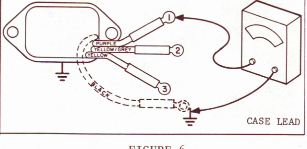
a. Momentarily short the purple clipper lead to case of clipper circuit.
b. Release purple lead and connect Ohmmeter as shown in Figure 6.
c. If meter reads greater than 300 ohms, proceed to Step 5.
d. If meter reads less than 300 ohms or if pointer moves toward zero ohms and returns to infinite ohms, replace clipper.
Step 5 -
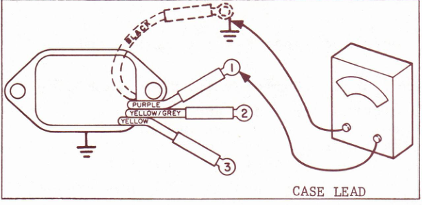
a. Momentarily short the purple clipper lead to case of clipper circuit.
b. Release purple lead and connect Ohmmeter as shown in Figure 7.
c. If meter pointer moves toward zero ohms and returns to infinity, clipper is good. Refer to your service manual or C.D. Troubleshooting Booklet and check for a failure of the charging circuit, C.D. ignition circuit, starter circuit, or shift circuit.
d. If meter pointer does not move, or goes to zero ohms and stays there, replace clipper.
JOHNSON MOTORS
Doug Cankar
Administrative Assistant
DC:rm
NOTE: Post on your 60 H.P. and 85 H.P. Indexes under the heading "Ignition."