SB-1241 - Remote Steering System Installation
Issued August 1970, this Johnson Service Bulletin documents mechanical push-pull and cable-pulley steering installation for 1970 33 through 115 HP outboards. The original ten-page factory publication is reproduced below with searchable instructions, kit part numbers, cable lengths and original technical figures.

SB-#1241
August, 1970
SUBJECT: REMOTE STEERING SYSTEM INSTALLATION
ON MODELS: 1970, 33 thru 115 H.P. Engines
Some of you may have noticed the new steering system instruction sheets which are being packed in the owner's kits of all 33 thru 115 H.P. engines. The recommendations stated in these sheets have come about after extensive testing by our Engineering Department and should be adhered to whenever you are rigging a boat. Following these instructions will insure a safe installation.
For your convenience we have consolidated these instructions below.
STEERING SYSTEM INSTALLATION INSTRUCTIONS FOR
1970, 33 AND 40 H.P. OUTBOARDS
1970, 33 AND 40 H.P. OUTBOARDS
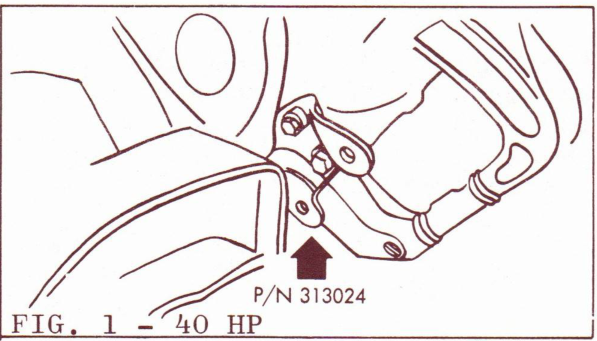
All 40 H.P. engines now come equipped with steering anchor bracket 313024 attached to the lower motor cover. This bracket is intended for use with mechanical (push-pull) type steering only. See Figure 1.
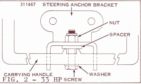
The 33 H.P. engines are not factory equipped with a steering bracket. Accessory Kit 380306 must be used when making a mechanical (push-pull) steering installation on a 33 H.P. engine. See Figure 2.
PAGE 2 SERVICE BULLETIN SB-#1241
JOHNSON MOTORS, DIVISION OF OUTBOARD MARINE CORPORATION, WAUKEGAN, ILLINOIS 60085
The following combination of OMC accessory kits is required for a mechanical steering installation.
These Kits include instructions which should be followed carefully for correct installation.
These Kits include instructions which should be followed carefully for correct installation.
| QUANTITY | PART NO. | DESCRIPTION |
|---|---|---|
| 1 | 171968 | Steering Wheel (172067 optional) |
| 1 | 171982 | Helm Assembly |
| 1 | See pg. 3 | Steering Cable of Selected Length |
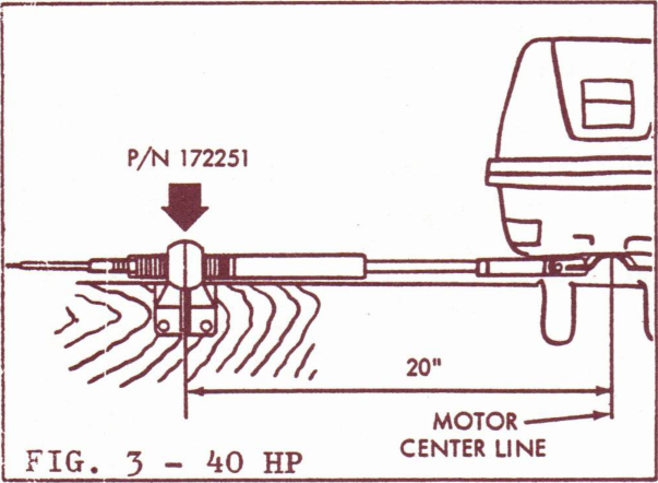
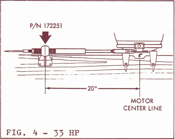
| 1 | 172251 | Terminal Hardware and Transom Bracket Kit (See Figures 3 & 4) |
| 1 | 380306 | Mechanical Steering Anchor Kit 33 H.P. only (See Figure 2) |
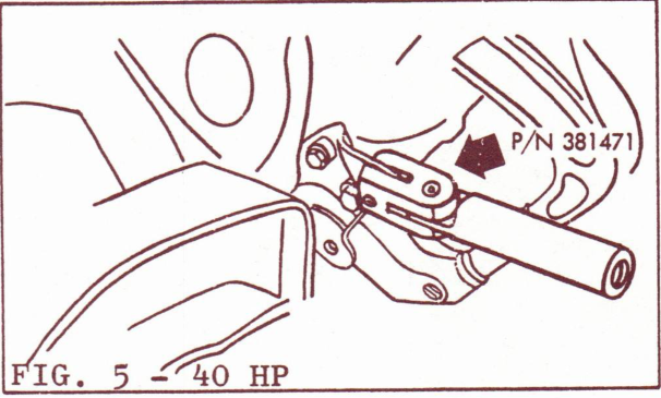
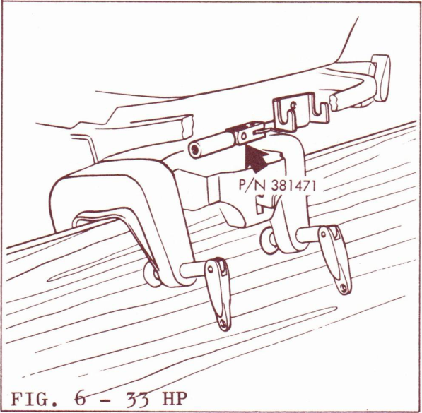
| 1 | 381471 | Steering Connector Kit (See Figures 5 & 6) |
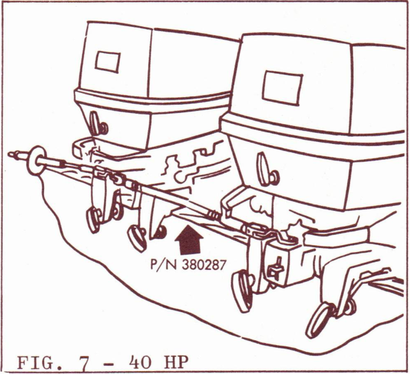
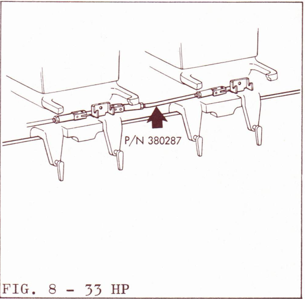
| 1 | 380287 | Dual Steering Connector Kit. Required for dual motor installations only (See Figures 7 & 8) |
NOTE
Steering Kit #380306 contains steering anchor bracket #311467. This bracket is to be used with mechanical (push-pull) steering installations only.
Steering Kit #380306 contains steering anchor bracket #311467. This bracket is to be used with mechanical (push-pull) steering installations only.
PAGE 3 SERVICE BULLETIN SB-#1241
JOHNSON MOTORS, DIVISION OF OUTBOARD MARINE CORPORATION, WAUKEGAN, ILLINOIS 60085
HOW TO MEASURE CABLE FOR MECHANICAL PUSH-PULL STEERING
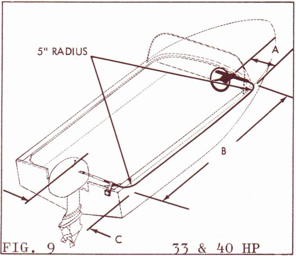
To determine length of cable required, measure along cable path from center of helm to connection point at engine (when engine is in "straight ahead" position). Be sure to allow for a 5" minimum radius bend of cable. If it is not possible to measure along cable path, use method outlined below.
1. Select a path from helm to engine that is as free as possible from obstructions.
2. Measure length of cable needed from center point of helm to engine connections point. (See Figure 9)
3. Calculate cable length using this formula. A+B+C=Approximate cable length.
2. Measure length of cable needed from center point of helm to engine connections point. (See Figure 9)
3. Calculate cable length using this formula. A+B+C=Approximate cable length.
Cables are available in one foot increments from ten feet through forty feet.
STEERING CABLES FOR SINGLE STATION
PART NO. LENGTH PART NO. LENGTH PART NO. LENGTH
172010 10' 172022 22' 172034 34'
172011 11' 172023 23' 172035 35'
172012 12' 172024 24' 172036 36'
172013 13' 172025 25' 172037 37'
172014 14' 172026 26' 172038 38'
172015 15' 172027 27' 172039 39'
172016 16' 172028 28' 172040 40'
172017 17' 172029 29'
172018 18' 172030 30'
172019 19' 172031 31'
172020 20' 172032 32'
PART NO. LENGTH PART NO. LENGTH PART NO. LENGTH
172010 10' 172022 22' 172034 34'
172011 11' 172023 23' 172035 35'
172012 12' 172024 24' 172036 36'
172013 13' 172025 25' 172037 37'
172014 14' 172026 26' 172038 38'
172015 15' 172027 27' 172039 39'
172016 16' 172028 28' 172040 40'
172017 17' 172029 29'
172018 18' 172030 30'
172019 19' 172031 31'
172020 20' 172032 32'
PAGE 4 SERVICE BULLETIN SB-#1241
JOHNSON MOTORS, DIVISION OF OUTBOARD MARINE CORPORATION, WAUKEGAN, ILLINOIS 60085
SECOND STATION CABLES
PART NO. LENGTH
172170 8'
172003 10'
172004 12'
172005 14'
172006 16'
172007 18'
172008 20'
172002 22'
PART NO. LENGTH
172170 8'
172003 10'
172004 12'
172005 14'
172006 16'
172007 18'
172008 20'
172002 22'
HOW TO INSTALL A PULLEY-CABLE STEERING SYSTEM
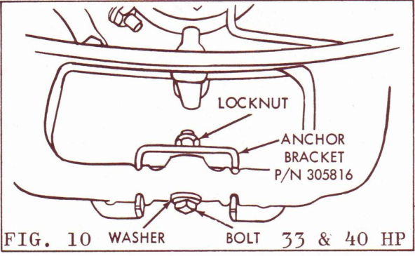
If Cable-Pulley steering is desired, accessory kit 379568 must be installed on carrying handle as illustrated. See Figure 10.
DO NOT install a cable-pulley system on push-pull anchor brackets 311467 (33 H.P.) or 313024 (40 H.P.). These brackets are for use with mechanical push-pull steering systems only.
If Cable-Pulley steering is desired, accessory kit 379568 must be installed on carrying handle as illustrated. See Figure 10.
DO NOT install a cable-pulley system on push-pull anchor brackets 311467 (33 H.P.) or 313024 (40 H.P.). These brackets are for use with mechanical push-pull steering systems only.
The following combination of OMC accessory kits is required for a cable and pulley installation.
| QUANTITY | PART NO. | DESCRIPTION |
|---|---|---|
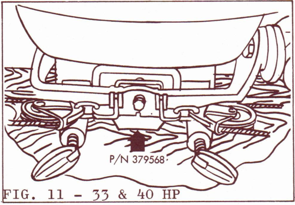
| 1 | 379568 | Steering Connector Kit (See Figure 11) |
| 1 | 171968 | Steering Wheel (172067 optional) |
| 1 | 171873 | Helm Assembly |
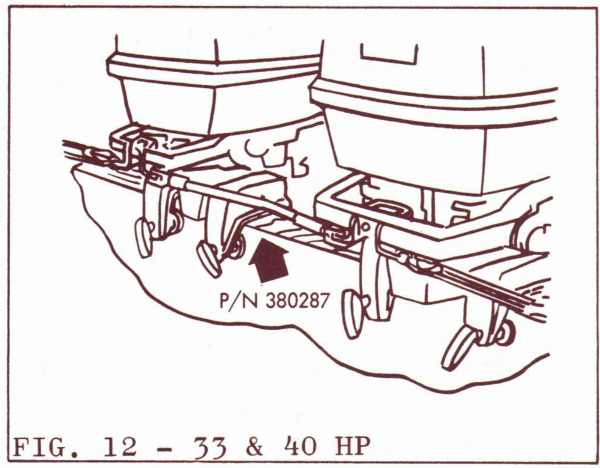
| 1 | 380287 | Dual Steering Connector Kit (Required for dual motor installations only. See Figure 12) |
CAUTION: Do not connect a mechanical push-pull cable system to a pulley-cable system anchor bracket 305816.
PAGE 5 SERVICE BULLETIN SB-#1241
JOHNSON MOTORS, DIVISION OF OUTBOARD MARINE CORPORATION, WAUKEGAN, ILLINOIS 60085
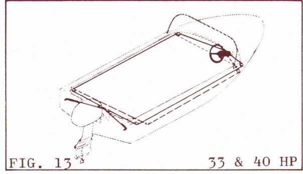
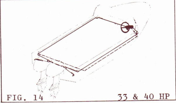
1. Install the cables as shown in Figure 13 for a single motor installation or Figure 14 for a dual installation.
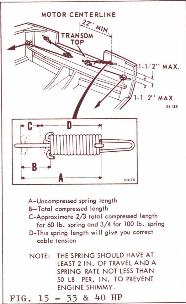
2. Steering system backlash can occur due to dimensional changes in your boat (due to moisture or dryness). To eliminate this backlash, install a spring in the steering system where one cable end is attached to the transom. Use a 60 lb. spring, tightening the steering cable so that the spring is compressed approximately two-thirds of total compressed length. This will put a 40 lb. load on the spring.
On some boats, fishtailing may occur at higher speeds and a stronger spring may be needed. You can use a 100 lb. spring, compressed approximately three-quarters of total compressed length. This will give a 75 to 80 lb. load on the spring. See Figure 15.
3. Do not use the spring to compensate for improper pulley or cable anchor positioning.
2. Steering system backlash can occur due to dimensional changes in your boat (due to moisture or dryness). To eliminate this backlash, install a spring in the steering system where one cable end is attached to the transom. Use a 60 lb. spring, tightening the steering cable so that the spring is compressed approximately two-thirds of total compressed length. This will put a 40 lb. load on the spring.
On some boats, fishtailing may occur at higher speeds and a stronger spring may be needed. You can use a 100 lb. spring, compressed approximately three-quarters of total compressed length. This will give a 75 to 80 lb. load on the spring. See Figure 15.
3. Do not use the spring to compensate for improper pulley or cable anchor positioning.
PAGE 6 SERVICE BULLETIN SB-#1241
JOHNSON MOTORS, DIVISION OF OUTBOARD MARINE CORPORATION, WAUKEGAN, ILLINOIS 60085
STEERING SYSTEM INSTALLATION INSTRUCTIONS
FOR 1970 60, 85 AND 115 H.P. OUTBOARDS
FOR 1970 60, 85 AND 115 H.P. OUTBOARDS
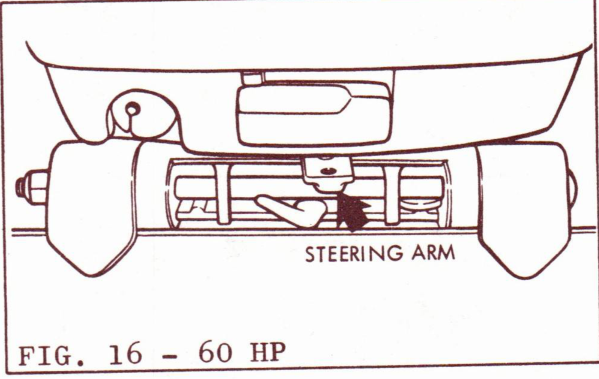
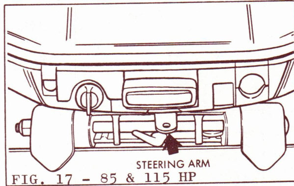
As delivered, all 60, 85 and 115 H.P. engines are ready for installation of mechanical (push-pull) type steering. See Figure 16 and 17.
The following combination of OMC accessory kits is required for a mechanical steering installation:
| QUANTITY | PART NO. | DESCRIPTION |
|---|---|---|
| 1 | 171968 | Steering Wheel (172067 optional) |
| 1 | 171982 | Helm Assembly |
| 1 | See pg. 3 | Steering Cable of Selected Length |
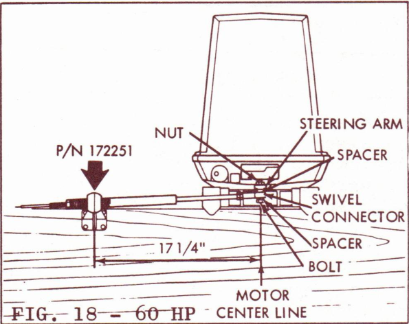
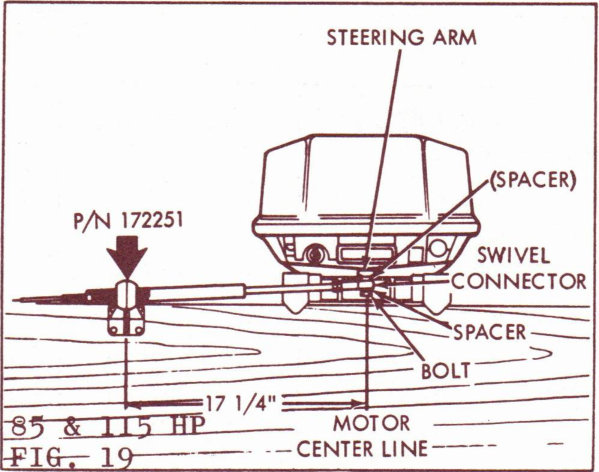
| 1 | 172251 | Terminal Hardware and Transom Bracket Kit (See Figures 18 & 19) |
NOTE: These Kits include instructions which should be followed carefully for correct installation.
PAGE 7 SERVICE BULLETIN SB-#1241
JOHNSON MOTORS, DIVISION OF OUTBOARD MARINE CORPORATION, WAUKEGAN, ILLINOIS 60085
HOW TO MEASURE CABLE FOR MECHANICAL PUSH-PULL STEERING
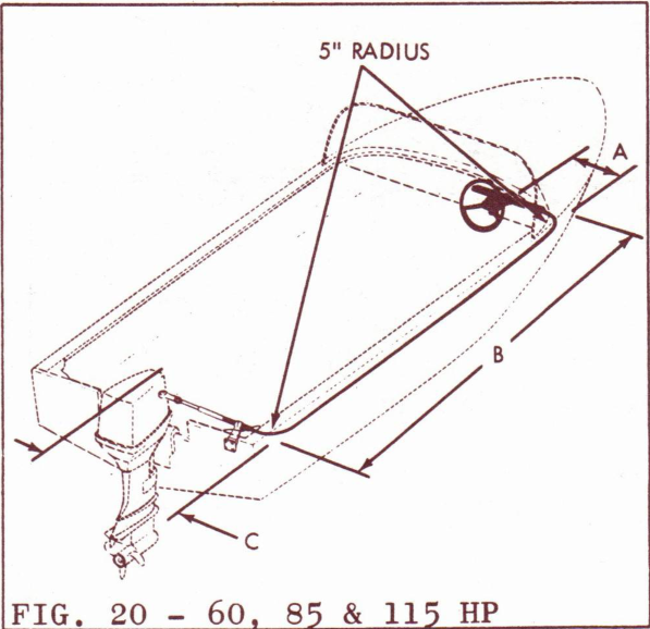
To determine length of cable required, measure along cable path from center of helm to connection point at engine (when engine is in "straight ahead" position). Be sure to allow for a 5" minimum radius bend of cable. If it is not possible to measure along cable path, use method outlined below.
1. Select a path from helm to engine that is as free as possible from obstructions.
2. Measure length of cable needed from center point of helm to engine connection point. (See Figure 20)
3. Calculate cable length using this formula: A+B+C=Approximate cable length.
Cables are available in one foot increments from ten feet through forty feet. (See page 3 and 4)
2. Measure length of cable needed from center point of helm to engine connection point. (See Figure 20)
3. Calculate cable length using this formula: A+B+C=Approximate cable length.
Cables are available in one foot increments from ten feet through forty feet. (See page 3 and 4)
HOW TO INSTALL A PULLEY-CABLE STEERING SYSTEM
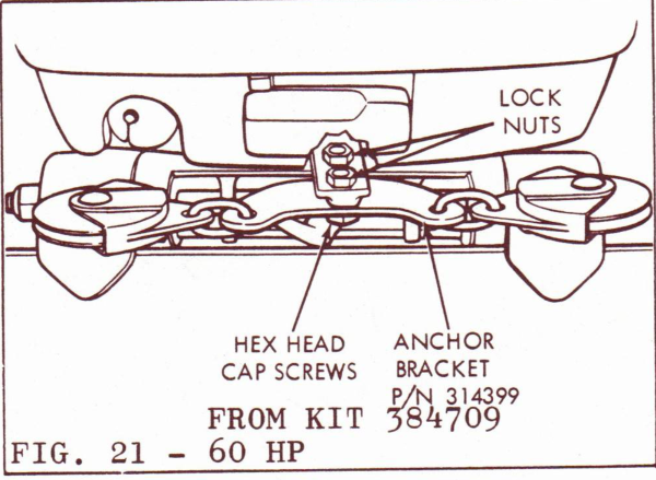
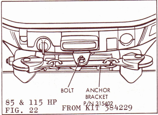
If Cable-Pulley steering is desired, accessory kit 384709 (60 H.P.) or 384729 (85 & 115 H.P.) must be used. These kits contain the correct anchor bracket which must be installed on the steering arm as illustrated. See Figures 21 & 22. Do not install a pulley-cable system directly to the engine steering arm.
NOTE: Torque locknuts to 15 to 20 foot pounds.
NOTE: Torque locknuts to 15 to 20 foot pounds.
PAGE 8 SERVICE BULLETIN SB-#1241
JOHNSON MOTORS, DIVISION OF OUTBOARD MARINE CORPORATION, WAUKEGAN, ILLINOIS 60085
The following combination of OMC accessory kits is required for a cable and pulley steering installation.
| QUANTITY | PART NO. | DESCRIPTION |
|---|---|---|
| 1 | 384709 | Steering Connector Kit (60 H.P.) (See Figure 21) (Two required for a dual motor installation) |
| 1 | 384729 | Steering Connector Kit - 85 & 115 H.P. (See Figure 22) (Two required for a dual motor installation) |
| 1 | 171968 | Steering Wheel (172067 optional) |
| 1 | 171873 | Helm Assembly |
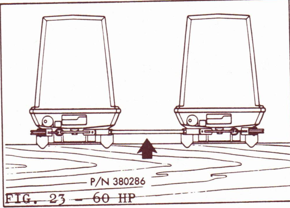
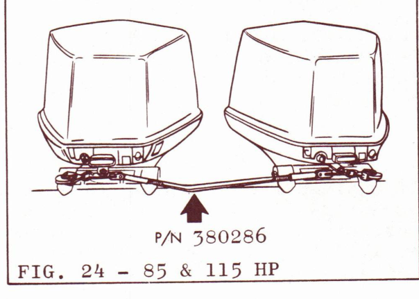
| 1 | 380286 | Dual Steering Connector Kit (Required for dual motor installations only. See Figures 23 & 24) |
CAUTION
Do not connect a mechanical push-pull cable system to pulley-cable system anchor brackets 314399 (60 H.P.) or 315402 (85 & 115 H.P.).
Do not connect a mechanical push-pull cable system to pulley-cable system anchor brackets 314399 (60 H.P.) or 315402 (85 & 115 H.P.).
PAGE 9 SERVICE BULLETIN SB-#1241
JOHNSON MOTORS, DIVISION OF OUTBOARD MARINE CORPORATION, WAUKEGAN, ILLINOIS 60085
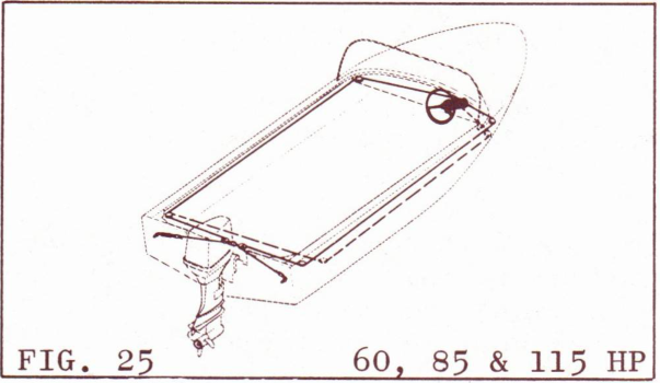
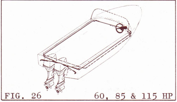
1. Install the cables as shown in Figure 25 for a single motor installation or Figure 26 for a dual installation.
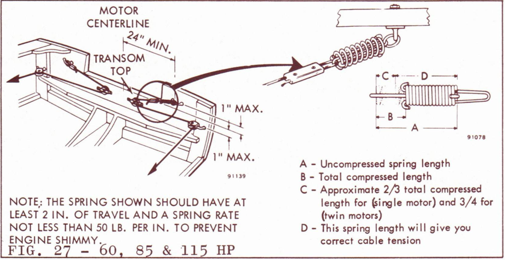
2. Steering system backlash can occur due to dimensional changes in your boat (due to moisture or dryness). To eliminate this backlash, install a spring in the steering system where one cable end is attached to the transom. Use a 60 lb. spring, tightening the steering cable so that the spring is compressed approximately two-thirds of total compressed length. This will put a 40 lb. load on the spring.
2. Steering system backlash can occur due to dimensional changes in your boat (due to moisture or dryness). To eliminate this backlash, install a spring in the steering system where one cable end is attached to the transom. Use a 60 lb. spring, tightening the steering cable so that the spring is compressed approximately two-thirds of total compressed length. This will put a 40 lb. load on the spring.
On some boats, fishtailing may occur at higher speeds and a stronger spring may be needed. You can use a 100 lbs. spring, compressed to approximately three-quarters of total compressed length. This will give a 75 to 80 lbs. load on the spring. See Figure 27.
3. Do not use the spring to compensate for improper pulley or cable anchor positioning.
3. Do not use the spring to compensate for improper pulley or cable anchor positioning.
PAGE 10 SERVICE BULLETIN SB-#1241
JOHNSON MOTORS, DIVISION OF OUTBOARD MARINE CORPORATION, WAUKEGAN, ILLINOIS 60085
IN ANY REMOTE STEERING SET UP, OBSERVE THESE RULES:
1. Use only stainless steel attaching hardware - Never use brass. Do not substitute bolts, screws, and hardware of unknown quality for parts furnished in kits.
2. Always use locknuts, lockwashers and thru bolts when fastening steering components to boat. Large diameter washers should be used on all soft load bearing surfaces such as wood, fiberglass and thin gauge aluminum. Never use wood or lag screws.
3. Minimum fastener size on any boat steering attachments such as pulleys and steering attachment anchors should be 1/4 - 28 (i.e. 1/4 inches in diameter - 28 threads per inch).
4. Use only SAE fine series threads (i.e. 1/4 - 28, 5/16 - 24 and 7/16 - 20, etc.) for attaching any steering hardware. Fine series threads give maximum strength per diameter of threaded fasteners.
2. Always use locknuts, lockwashers and thru bolts when fastening steering components to boat. Large diameter washers should be used on all soft load bearing surfaces such as wood, fiberglass and thin gauge aluminum. Never use wood or lag screws.
3. Minimum fastener size on any boat steering attachments such as pulleys and steering attachment anchors should be 1/4 - 28 (i.e. 1/4 inches in diameter - 28 threads per inch).
4. Use only SAE fine series threads (i.e. 1/4 - 28, 5/16 - 24 and 7/16 - 20, etc.) for attaching any steering hardware. Fine series threads give maximum strength per diameter of threaded fasteners.
JOHNSON MOTORS
Doug Cankar
Technical Data Coordinator
Doug Cankar
Technical Data Coordinator
DC:rm
NOTE: Post on your 33 through 115 H.P. Indexes under the heading "Miscellaneous".
Historical reference
SB-1241 distinguishes mechanical push-pull steering from cable-pulley steering, specifies compatible brackets and connector kits, and provides cable sizing and fastener safety guidance. Consult the factory diagrams alongside the instructions for correct rigging.