
SB-#1249
December, 1970
SUBJECT: 50 HP TIMER BASE AND STATOR ASSEMBLY LEADS
MODEL: 50 ES (L) 71
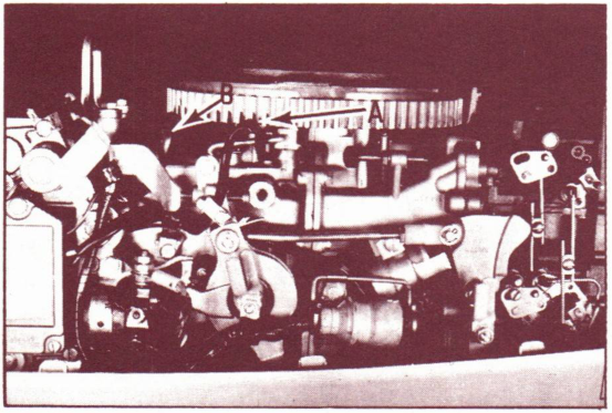
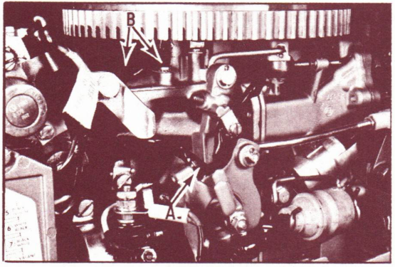
We have received a few reports of the flywheel making contact with the timer base and stator assembly leads. See figure 1-"A" & "B". This is particularly true of the timer base assembly leads shown at "A". Should this lead be grounded to the flywheel, an immediate power pack failure will result. Also, the timer base ass'y leads can (if not properly positioned) prevent full throttle operation, by becoming jammed between the throttle stop screw and spark advance lever. See figure 2-"A".
Before delivery or whenever a 50 HP motor comes into your shop, be sure to:
- Check the stator ass'y leads. If necessary push them in the direction of the arrows in fig. 2-"B", so they are clear of the flywheel.
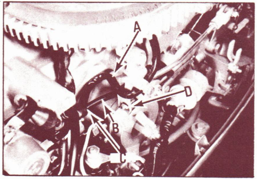
- Position the timer base lead excess slack at figure 3-"A".
- Use a screwdriver to push the clamp (Fig. 3-"C") all the way in against the cylinder and crankcase.
- Be sure the timer base leads are positioned on top of the choke solenoid leads. Fig. 3-"B".
- Advance the throttle fully and be sure the throttle stop screw clears the timer base leads at Fig. 3-"D".
JOHNSON MOTORS
Doug Cankar
Technical Data Coordinator
Doug Cankar
Technical Data Coordinator
NOTE: Post on your 50 HP indexes under the heading "Ignition".