SB-1282 - Service Information: 20 and 25 HP Erratic Idle
Issued January 1972, this Johnson Service Bulletin documents seven checks for erratic idling on 20 and 25 HP outboards, including carburetor and ignition synchronization and an exhaust-housing drilling diagram. The factory instructions are reproduced as searchable text.

SB-#1282
January, 1972
SUBJECT: Service Information
ON MODELS: All 20 and 25 H.P.
We have received a few reports from the field indicating that under
certain conditions, the idling on the 20-25 H.P. engines is erratic.
A number of check areas are outlined in this bulletin which you
should find helpful when attempting to correct conditions of less
than the desirable idle performance on the 20-25 H.P. engines. The
areas that may require attention will be listed under the following
group of headings:
1. Adjust carburetor as lean as possible so that the engine
passes through the 1000 RPM range smoothly.
2. Adjust the cam roller accurately so that the roller is
picked up precisely between the two marks on the cam.
3. Eliminate all play in the ignition cam.
4. Smooth the synchronization mark burrs and flashing from
the throttle cam.
5. Set points precisely and check with timing light with
engine running.
6. Check the coil lamination clearance with Tool #317001.
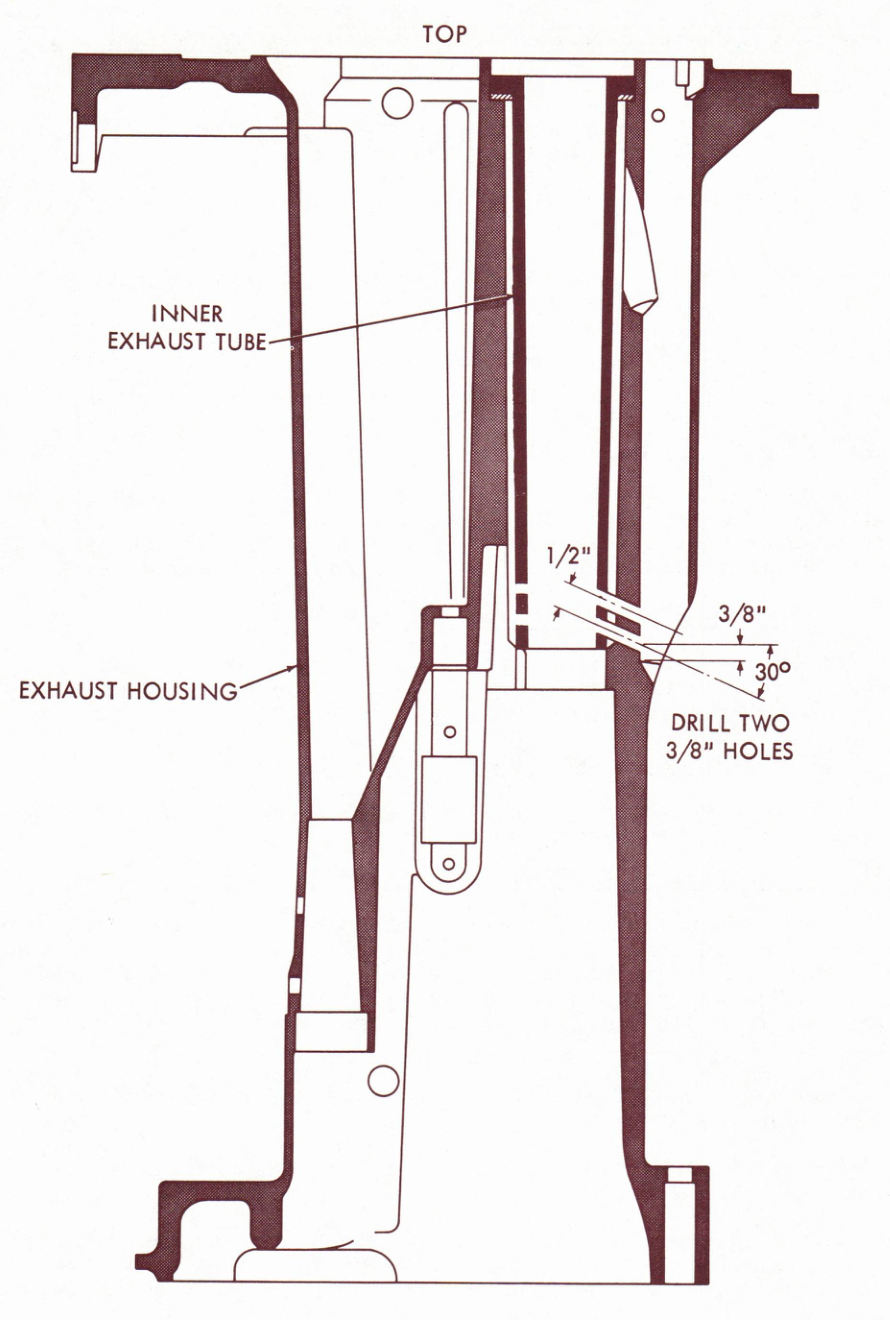
7. Drill two holes in the exhaust housing assembly #383913.
The first six steps listed above should correct any 20-25 H.P.
engines with erratic idling problems.
Proceed as follows:
1. ADJUST CARBURETOR
Let the engine idle at least 60 seconds before making any
adjustments. Adjust carburetor as lean as possible so that
the engine passes through the 1000 RPM range smoothly. 1/16"
of a turn can make a difference. This step is a very critical
operation in correcting the erratic idling problem.
(over)
PAGE 2 SERVICE BULLETIN SB-#1282
JOHNSON MOTORS, DIVISION OF OUTBOARD MARINE CORPORATION, WAUKEGAN, ILLINOIS 60085
2. ADJUST CAM ROLLER
Adjust the cam roller accurately so that the roller is picked up
precisely between the two marks on the cam.
The carburetor should begin to open when the roller is between the
two marks on the cam.
The method of adjustment is outlined in your service manuals.
Refer to your service manuals throughout this bulletin.
3. ELIMINATE PLAY IN CAM
Eliminate all play in the ignition cam. Refer to SB-#1266.
4. SMOOTH FACE OF THROTTLE CAM
When removing the burrs and flashing from the face of the throttle
cam, make sure you use a fine grade of sand paper. The use of a
file or coarse sand paper will change the contour of the face of
the throttle cam causing the engine to be out of synchronization.
5. SET POINTS AND CHECK WITH TIMING LIGHT
Set the points precisely as described in your service manual.
Check the timing with a timing light with the engine running as
outlined in your service manual.
6. CHECK COIL LAMINATION FOR PROPER CLEARANCE
Using tool part number #317001, properly locate the coils. This
is outlined in your service manual.
7. DRILLING THE EXHAUST HOUSING
Drill two 3/8" holes in the exhaust housing to relieve back pressure
as shown in the line drawing. Center bottom hole 5/16" up from the
arrow point. Drill the holes on a 30° angle - 3/8" center to
center. The angle of the holes and the location of the holes is
important to avoid drilling out the inner exhaust tube locating
boss.
We recommend you drill a 1/16" pilot hole before drilling the 3/8"
holes to prevent the bit from drifting.
Only drill into one side of the inner tube when drilling the two
holes.
Remove the gearcase and with a light, look up into the exhaust
housing to make sure that there is no carbon build up in the
inner tube. If there is a carbon build up, make sure you remove
it.
JOHNSON MOTORS
Doug Cankar
Technical Data Coordinator
Note: Post on your 20 & 25 H.P. Indexes under the heading "Miscellaneous".
Related bulletin: SB-1266 - Flywheel Key Installation, referenced in the factory text. Verify measurements and drilling positions against the original engineering illustration before performing any modification.