SB-1290 - Securing the 9½, 20 and 25 H.P. Propeller Nut
Issued March 1972, this Johnson Motors Service Bulletin explains the correct propeller nut tightening procedure to prevent drive pin wear and propeller hub damage on 9½, 20 and 25 H.P. outboards.

SB-#1290
March, 1972
SUBJECT: Securing the 9½, 20 and 25 H.P. Propeller Nut
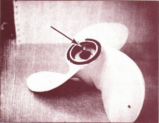
The stainless steel drive pin
used in the 9½, 20 and 25 H.P.
propeller will wear the inner
hub of the propeller, as shown,
to the point of complete failure
if the propeller nut is not
tightened properly.
This type of wear, resulting in
propeller failure, can be over-
come by securely tightening the
propeller nut. Secure the prop-
eller nut in the following
manner.
Insert the drive pin in the
propeller shaft, and place the
propeller in position. Install
the propeller nut, and secure
as tightly as possible by hand. With a wrench, advance the nut until
the cotter pin hole is in alignment and install and set cotter pin.
(DO NOT BACK THE NUT OFF TO ALIGN WITH THE NEXT COTTER PIN HOLE).
Securing the propeller in this manner will prevent it from floating on
the shaft causing hub damage.
JOHNSON MOTORS
Doug Cankar
Technical Data Coordinator
DC/sn
NOTE: Post on your 9½, 20 and 25 H.P. index under the heading
"Miscellaneous".
Historical factory service information. Refer to the applicable Johnson service manual for additional propeller installation and safety procedures.