Johnson Service Bulletin SB-1315 - New Neutral Detent Feature Added
Issued April 1973, this factory bulletin explains the new neutral detent in 1973 Johnson 50 through 135 H.P. gearcases, including production serial numbers, special tool dimensions, and assembly procedures.

SB-#1315
April, 1973
SUBJECT: New Neutral Detent Feature Added
ON MODELS: 1973, 50 thru 135 H.P. Gearcases
As the result of field and Florida tests, we decided to add the
shift detent feature to our 1973 thru hub exhaust gearcases.
This is primarily to improve shift dog life and aid the techni-
cian in locating the neutral position during cable installation.
Adjusting for correct forward and reverse overtravel will be
easier. The detented shift started with the following model and
serial numbers.
50ES73 65ES73 85ESL73 115ESL73 135ESL73
3813261 3880057 3859697 3867793 3875698
50ESL73 65ESL73
3821122 3843661
65ESLR73
3880940
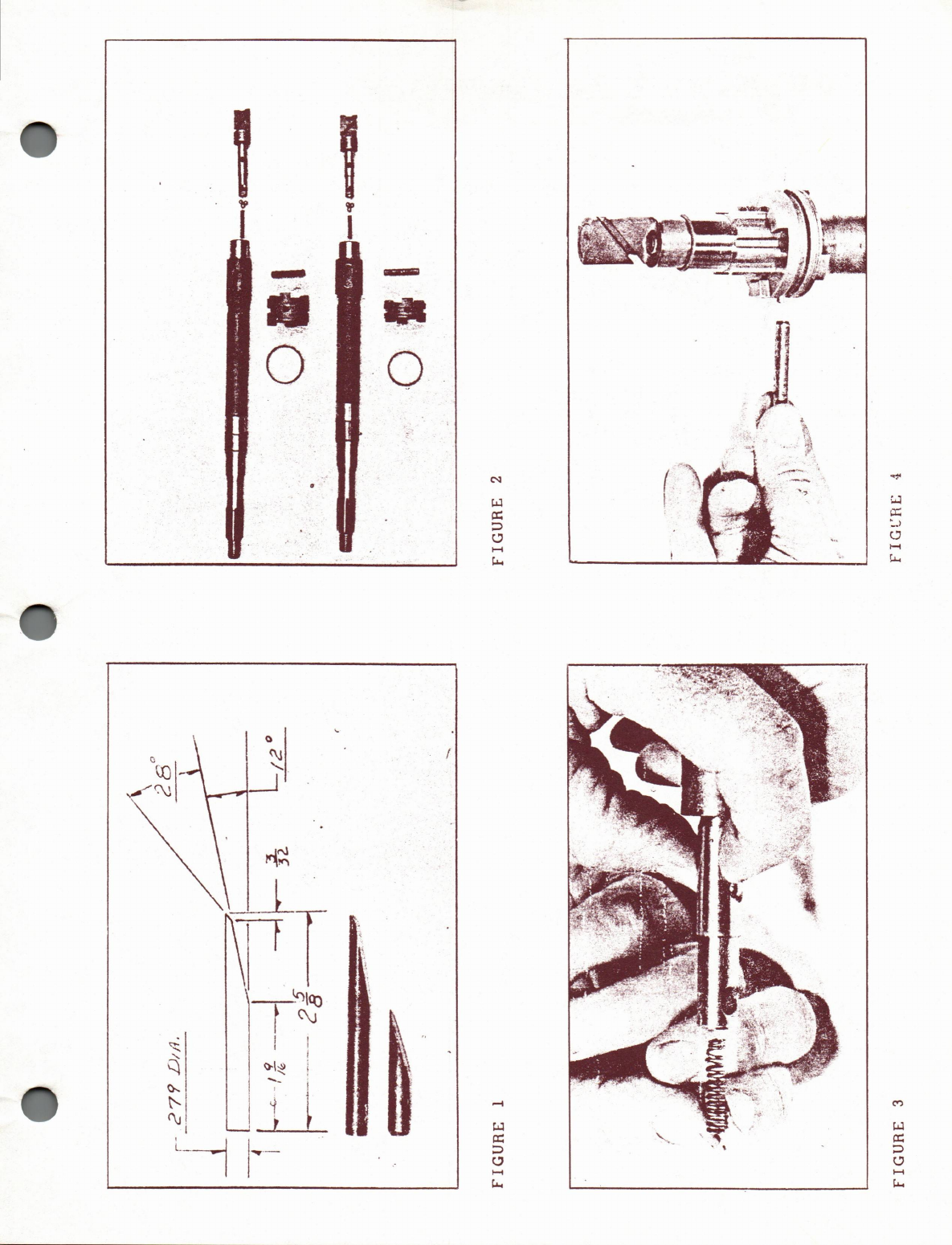
The following illustrations show how to make a tool, how to
assemble and disassemble the unit and how to tell the difference
between the parts used in the 50 or 65 H.P. and the V4's.
As shown in figure 1, the tool can be made using a .279 drill
rod or a P/N 313448 clutch dog pin. Since the tool made from
the drill rod is longer, it will be easier to use.
The 50 and 65 H.P. parts are at the bottom of figure 2. The propeller
shaft, clutch dog, clutch dog pin spring and shift rod are different
from the V4's and these differences can be seen in figure 2.
The detent activating springs are distinguishable by size and color.
The 50 and 65 H.P. spring, P/N 318575, is shorter and colored black.
The P/N 318576 used in the V4's is red and longer. The detent balls
P/N 316506 are the same and three are required.
As shown in figure 3, place two balls in the hole nearest the
plunger, then while holding them in place with thumb and forefinger,
drop in third ball from the top and drop the spring on top of it.
(over)
JOHNSON OUTBOARDS, DIVISION OF OUTBOARD MARINE CORPORATION, WAUKEGAN, ILLINOIS 60085
Now place the shift rod into the prop shaft being sure the hole
in the shifter dog lines up with the slot in the prop shaft and
shift rod.
As indicated in figure 4, with the flat or ground side facing the
detent spring, push the tool partially thru the hole. Start the
clutch dog pin into the hole then tap it thru with the plastic or
wooden end of a screwdriver. Replace the clutch dog pin spring
and the complete assembly can be installed in the gearcase.
Although the detented feature can be added to earlier 1973 engines,
it would require the prop shaft which is ground to accept the
detent balls, the shift rod with the holes for the detent balls,
the detent spring and three detent balls.
JOHNSON OUTBOARDS
D. J. Leinonen
Technical Data Coordinator
DL/sn
NOTE: Post on your 50 thru 135 H.P. under the heading "Gearcase"
FOOTNOTE: On page 2 of SB-#1302 under (PULLEY-CABLE STEERING
SYSTEM) please change P/N 386027 to read 384729.