
SB-#1321
June, 1973
SUBJECT: New Procedure for Adjusting Starter Lockout Lever
ON MODELS: 1973 20 & 25 H.P.
The new adjustment procedure described below should be used in place
of the procedure described in your 1973 service manual (page 8-4).
This new procedure will provide more consistent adjustment of the
lockout lever clearance gap and eliminate the possibility of the
locking lever engaging when the shift lever is in neutral.
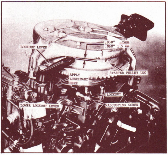
1. Apply a small amount of OMC Sea-Lube* anti-corrosion lubricant to
the lockout lever at its point of contact with the lower lockout
lever.
2. Place shift lever in neutral position. Loosen locknut and turn
adjusting screw so that the clearance between the lockout lever
and lug on starter pulley is 1/8". Now turn adjusting screw so
that a final clearance of .030" - .060" (.75-1.5mm) is obtained.
(over)
PAGE 2
SERVICE BULLETIN SB-#1321
JOHNSON OUTBOARDS, DIVISION OF OUTBOARD MARINE CORPORATION, WAUKEGAN, ILLINOIS 60085
3. Move the shift lever to forward, reverse, and back to neutral.
Recheck the lever to lug clearance. Clearance should be less
than .090" (2.3mm). If clearance is greater than .090" (2.3mm),
readjust following step 2. After correct adjustment is obtained,
lock the adjusting screw with locknut.
NOTE
It is important that you always start with excess clearance (1/8" or
3.18mm) and adjust down to .030" - .060" (.75-1.5mm). Simply increasing
clearance from zero to .030" - .060" (.75-1.5mm) will usually result in
an inconsistent final clearance.
JOHNSON OUTBOARDS
D. J. Leinonen
Technical Data Coordinator
DL/sn
NOTE: Post on your 20 & 25 H.P. index under the heading "Powerhead".
FOOTNOTE: Please change your 9R73 service manual page 2-2 coil
specifications for coil 580971. Use B scale with coil
index of 22 for the Stevens Magneto Analyser, change
Stevens specification page to read use B scale and index
22.