Johnson Service Bulletin SB-1336 (February 1974) - Spark Plug Fouling
Factory troubleshooting instructions for spark plug fouling and hard starting on 1974 Johnson 9.9 and 15 HP outboards, including choke operation, spark plug and ignition checks, throttle cam adjustment, and low-speed carburetor settings.
February, 1974
SUBJECT: Spark Plug Fouling
MODELS: 1974, 9.9 & 15 H.P.
We have received several complaints of oil fouled spark plugs on 9.9 & 15 H.P. engines during trolling or commercial use. If you have a customer complaint of this type, we suggest you first determine if the problem is really plug fouling (by oil) or if it is a hard starting condition (resulting in wet plugs). If the customer indicates that the engine is unusually difficult to start, particularly when warm, we suggest the following.
1. Examine the choke valve. If it does not have any air bleed holes, it should be replaced using 320267 on 9.9 H.P. or 320268 on 15 H.P. (Per Johnson Service Bulletin SB-#1330)
2. Disconnect throttle cracker. This can be done by cutting and removing the link (319020) running between the choke lever and the throttle advance lever.
3. Check operation of choke knob. A properly operating choke will move in and out smoothly, but in some cases a firm pull is required to insure reaching the full choke position. When in the full choke position, the face of knob will be out further than the end of the rewind starter handle. See figure 1.
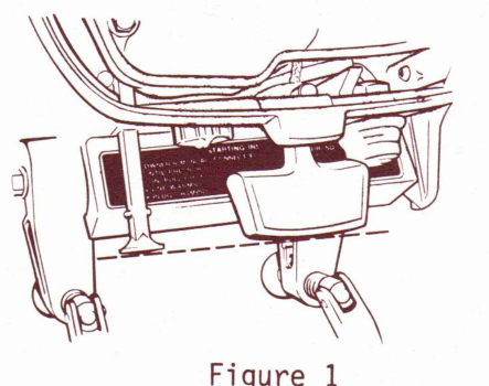
Figure 1
4. Instruct the customer to squeeze the primer bulb each time he starts the engine, even if it has been run recently.
5. Instruct the customer to pull starter handle slowly until the starter pinion engages the flywheel, then pull the rope quickly to assure adequate starting RPM.
If the problem is determined to be plug fouling (by oil), make the following checks and adjustments:
(over)
1. Replace the spark plugs making sure the new plugs are Champion L-7J's (OMC P/N 386035) gapped to .030". This spark plug will be available from your distributor or the Champion outlets if your distributor cannot supply your requirements.
2. Remove boots and springs from spark plug wires. Clean wires and boots thoroughly with solvent. Reinstall spring & lubricate wire end with OMC Sea-Lube* multi-purpose grease. Reinstall boot and secure to wire with a P/N 320107 tie strap. Reposition wire clamps on cylinder head cover and relocate spark plug wires as shown. See figure 2. Remove foam blanket from motor cover.
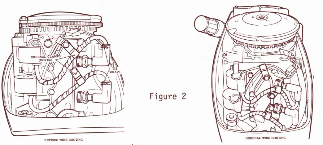
Figure 2
 SAFETY WARNING
Do not use auxiliary gap spark plugs in engines which have tie straps on boots. Champion brand auxiliary gap spark plugs are identified by the prefix "U" (as in UL-4J).
3. Make sure the fuel/oil mix is not overly rich and that the oil being used is BIA certified for service TC-W.
4. Use a 12 volt power timing light and check the ignition timing on both upper & lower cylinder (engine at normal idle speed).
Run engine up and down from 800-1200 RPM and listen for a knocking noise in the flywheel area. The knocking noise would indicate that the coil laminations are hitting the flywheel. A quick check to determine if they are is to operate the engine over the noisy RPM range while carefully touching the underside of the magneto plate with your hand. If the laminations are hitting the flywheel, you'll feel the striking force in your hand.
SAFETY WARNINGKEEP HANDS CLEAR OF FLYWHEEL
5. Check the output of the ignition coils using a spark gap tester set to 7/16". See figure 3. Refer to page 4-4 of your service manual for step-by-step procedure.
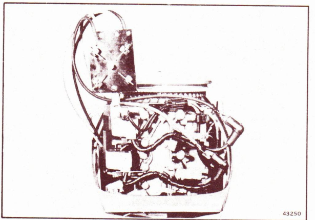
Figure 3
6. If engine did not pass tests in steps 3 & 4, remove the flywheel and do the following:
a. If the ignition timing check made in step 4 indicated that the breaker points were out of adjustment, reset them using a timing fixture (special tool 386656). Refer to pages 4-11 and 4-12 of your service manual for step-by-step procedure.
b. If you detected a knocking noise in step 4 or a weak spark in step 5, inspect the coil laminations to see if they have shifted. The lamination stack should be perfectly straight. If it isn't, the coil should be replaced. Make sure lamination heels of coils are flush with machined surfaces on armature plate. See figure 4. Replace flywheel & torque nut to 45-50 foot pounds.
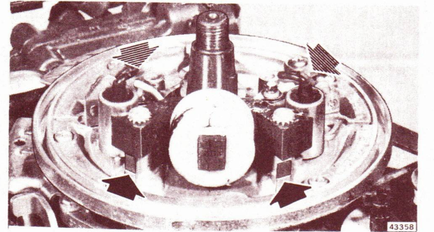
Figure 4
7. Check the throttle cam adjustment by advancing the throttle grip until "V" mark on cam points to center of cam follower roller. See figure 5. At this point throttle valve must be closed and roller must be touching cam. If not, loosen two cam screws and adjust cam as necessary. Tighten screw and check operation.
(over)
Throttle valve should just start to open as "V" mark passes center of roller.
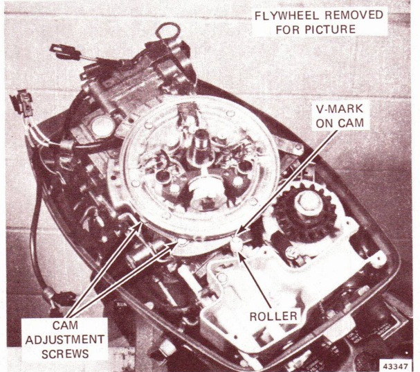
Figure 5
8. Pull the slow speed knob off and examine the inner end for missing pieces. See figure 6. If a segment of the knob is broken off, it may have been drawn through the carburetor where it could lodge between a leaf valve and the leaf plate. If one or more segments of the knob are missing, you should inspect the air silencer, carburetor bore and leaf plate.
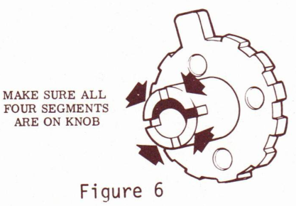
Figure 6
9. Check to make sure both low speed knob grommets are in place. See bulletin (Johnson - SB-#1328, Evinrude Fuel System 1029) for further information on this.
10. Adjust the low speed needle. Turn it in until it just seats and then back it out 7/8 turn on 9.9 H.P. engines or 1-3/8 turn on 15 H.P. engines. Reinstall the low speed knob so that its pointer is straight down. After installing the knob, check between the lower motor cover and the air silencer to make sure grommets were not disturbed. See figure 7. A warm engine should run properly with the low speed needle set to plus or minus 1/8 turn of the initial settings given above
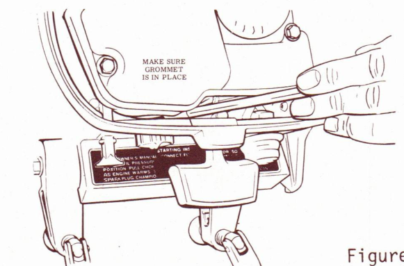
Figure 7
(3/4 to 1 turn on 9.9 H.P., 1 to 1-1/2 turn on 15 H.P.). Engines which do not operate acceptably well will have to be checked further. Areas to be checked include the thermostat to insure it is operating properly (use a thermomelt stick as explained on page 5-3 of your service manual); the carburetor throttle plate to make sure it closes fully and the by-pass covers or crankcase split line to insure there is no leakage. (The symptom of leakage at the by-pass cover or crankcase split line is backfiring on one cylinder. This backfiring occurs when the engine is running at the point where the throttle valve just starts to open (approximately 1200 RPM)).
Due to the combination of carburetor calibration and ignition advance used on early 9.9 & 15 H.P. engines, you may find some engines which are slightly lean when decelerating from wide open throttle to a slow idle. This lean condition may cause the engine to "pop" or backfire. Instructing the owner to pause briefly at 1000 RPM will eliminate the condition.
D. J. Leinonen
Technical Data Coordinator
DJL/sn
NOTE: Post on your 9.9 and 15 H.P. indexes under the heading "Ignition".