SB-1375 - Pulse Pack Service Tips
Issued in February 1975, this Johnson Service Bulletin describes an ignition safety-circuit starting problem on certain 1969-1970 115 H.P. outboards and provides a pulse-pack, rotor and voltage-suppressor compatibility chart for 1967-1968 100 H.P. models.

SB-#1375
February, 1975
SUBJECT: Pulse Pack Service Tips
ON MODELS: 1967 thru 1970 100 & 115 H.P.
I. There have been several isolated reports of 1969 and 1970
115 H.P. engines equipped with the ignition safety circuit
which, after having a replacement pulse pack (P/N 385038)
installed, will not start or will start only with great
difficulty. However, when the safety circuit is by-passed
with a jumper lead between the 7 and 8 or 9 terminals of
the terminal block, the engine starts and runs in a normal
manner.
115 H.P. engines equipped with the ignition safety circuit
which, after having a replacement pulse pack (P/N 385038)
installed, will not start or will start only with great
difficulty. However, when the safety circuit is by-passed
with a jumper lead between the 7 and 8 or 9 terminals of
the terminal block, the engine starts and runs in a normal
manner.
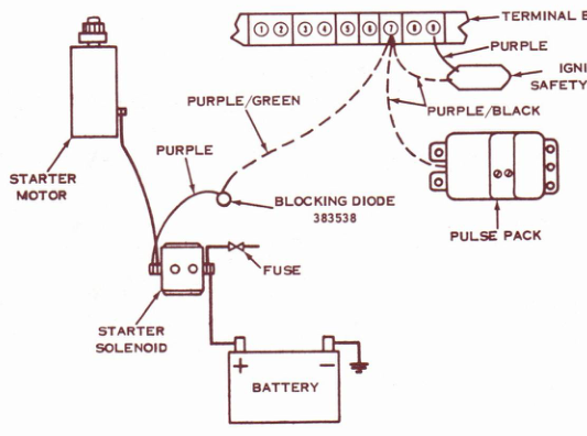
If you experience this problem, it can be corrected by
adding a blocking diode (P/N 383538) which has to be mod-
ified with spliced on long leads and terminals. Connect
the diodes' purple/green stripe lead to terminal 7 of
terminal block. Connect diodes' purple lead to starter at
same terminal where heavy starter motor lead is connected.
See schematic. Secure diode to by-pass cover with a clamp.
adding a blocking diode (P/N 383538) which has to be mod-
ified with spliced on long leads and terminals. Connect
the diodes' purple/green stripe lead to terminal 7 of
terminal block. Connect diodes' purple lead to starter at
same terminal where heavy starter motor lead is connected.
See schematic. Secure diode to by-pass cover with a clamp.
NOTE
Be sure to remove the temporary jumper lead
between 7 and 8 or 9 terminals so that safety
circuit will function properly.
between 7 and 8 or 9 terminals so that safety
circuit will function properly.
(over)
PAGE 2SERVICE BULLETIN #1375
JOHNSON OUTBOARDS, DIVISION OF OUTBOARD MARINE CORPORATION, WAUKEGAN, ILLINOIS 60085
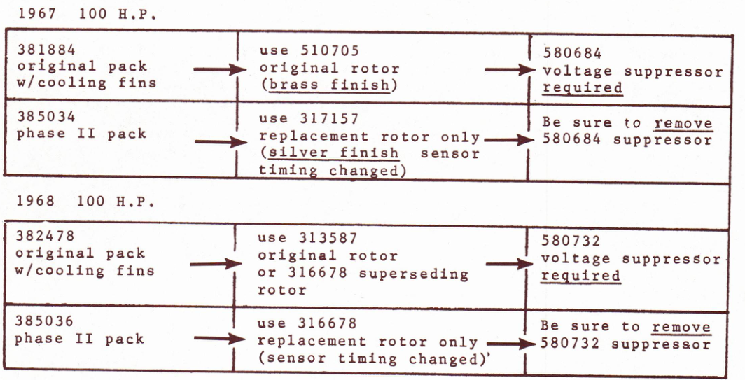
II. The chart below combines information from (Johnson bul-
letin SB-#1272) and the footnote from (Johnson bulletin
SB-#1322). Make sure the rotor used is as indicated in
the chart. The correct rotor is supplied with the phase
II packs. Also, make sure the voltage suppressor is
removed when a phase II pack is installed.
letin SB-#1272) and the footnote from (Johnson bulletin
SB-#1322). Make sure the rotor used is as indicated in
the chart. The correct rotor is supplied with the phase
II packs. Also, make sure the voltage suppressor is
removed when a phase II pack is installed.
JOHNSON OUTBOARDS
D. J. Leinonen
Technical Data Coordinator
Technical Data Coordinator
NOTE: Post on your 100 and 115 index under heading "Ignition".
DJL/kr
Related factory publications
SB-1272 and SB-1322 are referenced in the original bulletin's pulse-pack compatibility guidance.