SB-1392 - Permanently Installed Fuel Tanks
Issued October 1975 for the 1976 Johnson 200 H.P. V6, this factory bulletin explains fuel pressure testing and troubleshooting restrictions in permanently installed marine fuel tanks. Both pages are reproduced as searchable text, with the original testing schematic retained.
SB-#1392
October, 1975
SUBJECT: Permanently Installed Fuel Tanks
ON MODELS: 1976 200 H.P. V-6
NOTE
Built in fuel systems must be checked for re-
strictions as part of normal motor installation.
When permanent installed fuel tanks are used, some anti-siphon valves, primers, filters, etc. may present restrictions greater than can be tolerated by the engine fuel pumps. Too great a restriction could reduce fuel flow to the engine resulting in poor performance and possible engine damage. To check for restrictions, the following steps should be followed.
1. FUEL PUMP PRESSURE TEST
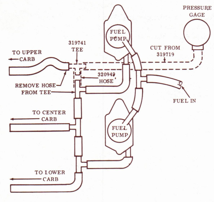
Install an automotive fuel pump testing gauge in the fuel line between the fuel pumps outlets and the carb inlets. See illustration. Make sure the fuel pump filters are clean. Run the engine at full throttle within its operating range until a stable fuel pressure is observed usually within one minute. Pressure must be between 2½ and 6 psi.
NOTE
Unless engine is broken-in do not run full throttle
for more than 1 minute without returning to part
throttle for a cooling period.
If the pressure is less than 2½ psi. disconnect the built-in tank and connect the 6 gallon tank (P/N 387410) supplied with the engine and repeat test.
If the pressure is below 2½ psi with the 6 gallon tank, replace fuel pumps (P/N 387470) and repeat test.
If the pressure with 6 gallon tank is above 2½ psi, but lower with the built-in fuel system, there is a problem in the boat fuel system.
PAGE 2 SERVICE BULLETIN #1392
JOHNSON OUTBOARDS, DIVISION OF OUTBOARD MARINE CORPORATION, WAUKEGAN, ILLINOIS 60085
2. CHECKING & CORRECTING OF BUILT-IN FUEL SYSTEMS
Use #376156 fuel connector, #173245 primer bulb and no more than 6' of ¼ I.D. flexible hose #321236 to connect the tank to the engine. These are the same parts included with OMC 6 gallon tank #387410 supplied with engine.
If the tank is located so that more than 6' of line is required, it must be at least 5/16" minimum I.D. between tank and primer bulb. OMC #319719 flexible hose or 3/8" O.D. copper tubing are satisfactory. All fittings must be a minimum of ¼" I.D. Be sure lines are free of kinks or sharp bends.
Do not use auxiliary filters other than the tank pickup tube screen.
Do not use OMC Primer pump #377381.
If the lines and fitting are correct and the pressure still checks below 2½ psi in systems with an anti-siphon valve, temporarily by-pass the valve with a length of #319719 hose. If this corrects the problem, replace the anti-syphon valve with one of these OMC anti-syphon valves:
P/N 173273 for 5/16" I.D. hose
P/N 173274 for 3/8" I.D. Hose
P/N 173275 for 3/8" O.D. Copper Tube
NOTE
When using standard 6 gallon fuel tanks be sure to use 387410 which is designed for V-6 use. Do not use the standard 4 or 6 gallon OMC tanks or hoses since they may not allow ample fuel flow.
When using standard 6 gallon fuel tanks be sure to use 387410 which is designed for V-6 use. Do not use the standard 4 or 6 gallon OMC tanks or hoses since they may not allow ample fuel flow.
JOHNSON OUTBOARDS
D. J. Leinonen
Technical Data Coordinator
D. J. Leinonen
Technical Data Coordinator
DJL/kr
NOTE: Post on your V-6 index under heading "Carburetion."
NOTE: Post on your V-6 index under heading "Carburetion."