Johnson Service Bulletin SB-1403 Rev. 1 - Ammeter Kits
Issued January 1976, this revised bulletin explains charging problems caused by installing ammeter kits 172994 and 172995 on 1976 Johnson V-6 200 H.P. outboards. The second page provides original wiring diagrams and modification instructions.

January, 1976
SUBJECT: Ammeter Kits P/N 172994 and P/N 172995
ON MODELS: V-6 1976
Use of the subject kits on the 1976 Johnson 200 h.p. causes a problem with the new two-wire regulator used on this engine. When the ammeter is connected per instructions, the regulator operates at a lower battery voltage resulting in less charging current being supplied to the battery; therefore, subject kits should not be installed on 200 h.p. outboards.
On kits already installed, if low charging current is a problem and it is desired to retain the ammeter function, change the wiring as shown on back of bulletin. Replace the regulator with part number 581580, obtain lead assembly part number 172761. The leads on this regulator should be connected the same as the one removed except that the additional red lead should be connected to terminal #6 on the terminal board.
The regulator is being changed on V-6 engines for 1977 and later models to facilitate use of subject ammeter kits.
D. J. Leinonen
Technical Data Coordinator
NOTE: Post on your V-6 index under heading "Electrical" and on
your miscellaneous index under heading "Accessories".
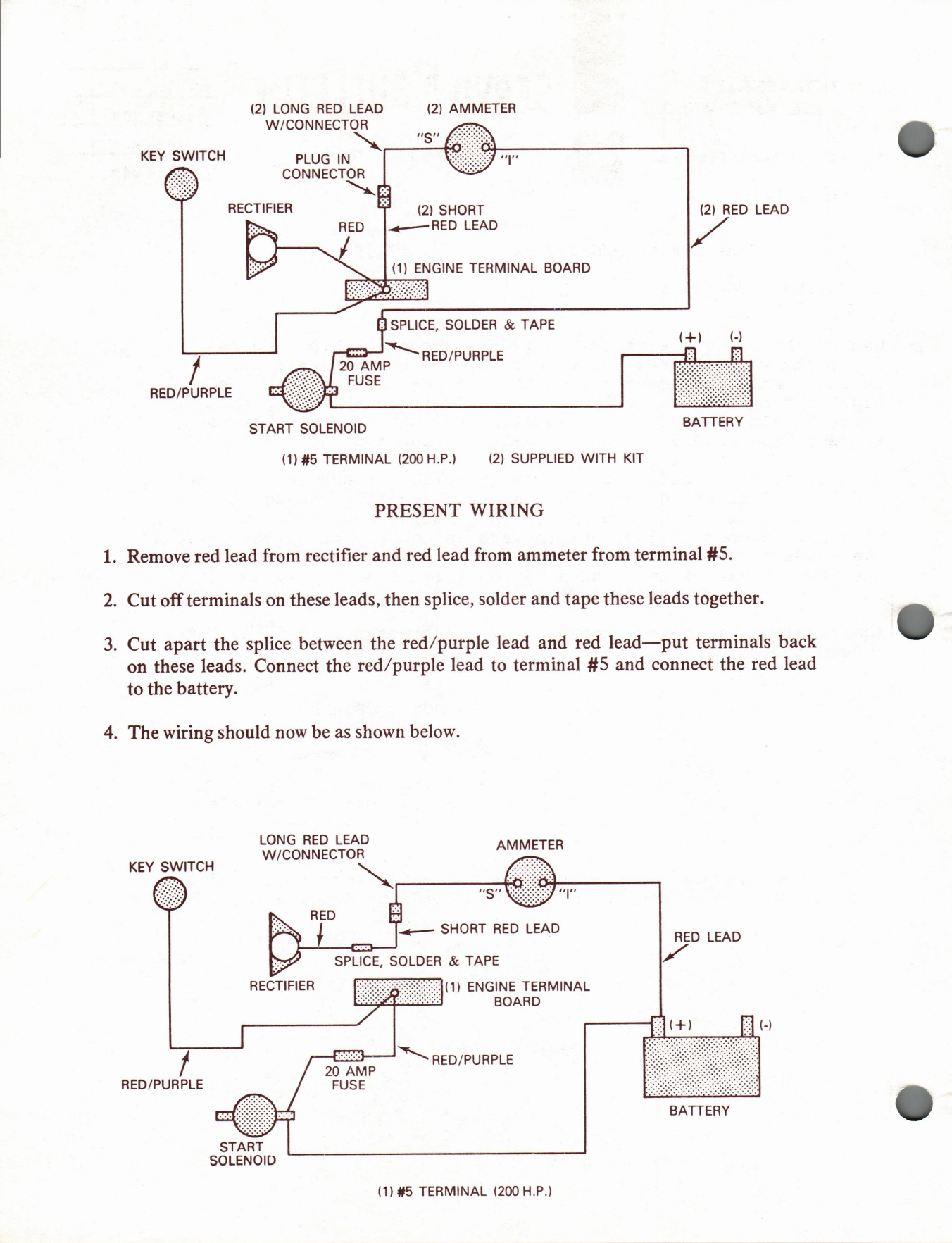
Searchable transcription of page 2 instructions
PRESENT WIRING

1. Remove red lead from rectifier and red lead from ammeter from terminal #5.

2. Cut off terminals on these leads, then splice, solder and tape these leads together.

3. Cut apart the splice between the red/purple lead and red lead - put terminals back on these leads. Connect the red/purple lead to terminal #5 and connect the red lead to the battery.

4. The wiring should now be as shown below.

Diagram labels: KEY SWITCH; RECTIFIER; AMMETER; ENGINE TERMINAL BOARD; RED/PURPLE; START SOLENOID; 20 AMP FUSE; BATTERY; LONG RED LEAD W/CONNECTOR; SHORT RED LEAD; SPLICE, SOLDER & TAPE.
Related technical information: 1976 Johnson V-6 charging system and ammeter installation.