Back to previous page

SB-1446 - Troubleshooting V4 and V6 Tilt and Trim Units

Issued November 1977, this eight-page Johnson Service Bulletin provides a factory troubleshooting guide for V4 and V6 hydraulic tilt and trim units. The symptom checklist, amperage reference table, pressure specifications, and service procedures are reproduced as searchable text. Factory hydraulic flow schematics and equipment illustrations are preserved.

Johnson Service Bulletin factory letterhead
SB-#1446

November, 1977

SUBJECT: TROUBLESHOOTING THE V-4 AND V-6 TILT AND TRIM UNITS

To aid dealers in troubleshooting the V-4 and V-6 tilt and trim units we have developed a comprehensive service bulletin including a quick reference troubleshooting guide, an amperage versus time comparison chart, and schematics that show oil pressure and flow.

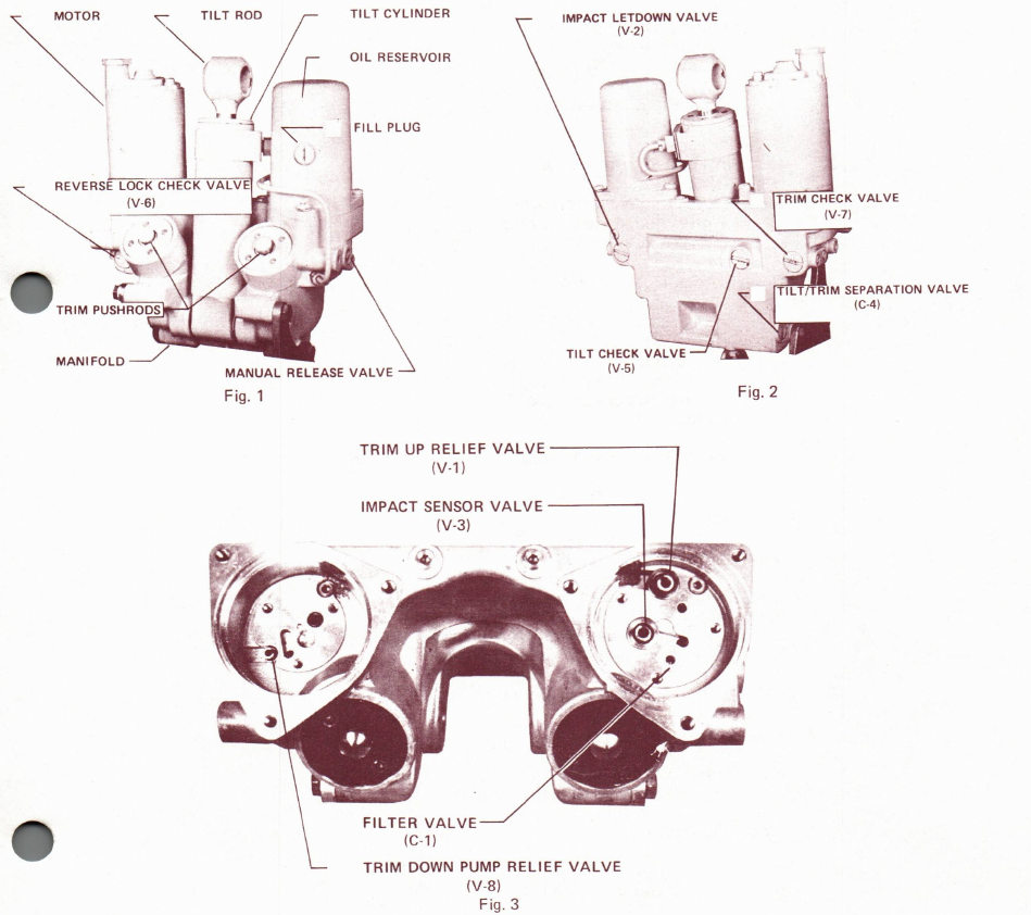
Figures 1, 2, 3: tilt and trim unit valve and component identification
PAGE 2SERVICE BULLETIN #1446JOHNSON OUTBOARDS, DIVISION OF OUTBOARD MARINE CORPORATION, WAUKEGAN, ILLINOIS 60085

These three views show the various parts of the tilt/trim unit. This nomenclature will be used in 1978 service manuals to aid in proper identification of parts.

NOTE: Cleanliness is an absolute must in working on the tilt/trim units since small particles of sand, salt, metal, etc., may prevent a valve from seating properly resulting in leak down or other malfunctions.

A. Quick reference trouble shooting - to locate the cause of the malfunction quickly.

  1. Tilt Leakdown (No Leak in Trim Range)
    1. Trim up relief valve
    2. Manual release
    3. Tilt cylinder valve or seals
    4. Tilt check valve
    5. Impact letdown valve
    6. Oil lines
  2. Leaks in Tilt and Trim Range
    1. Trim cylinders piston seals *
    2. Trim cylinders sleeve o-rings
    3. Trim check valve
  3. Reverse Lock Does Not Hold
    1. Impact sensor valve **
    2. Filter valve seat
    3. Manual release
    4. Tilt cylinder valves or seals
    5. Reverse lock check valve
    6. Oil lines
  4. Trim Rods Pull In When Reverse Lock Does Not Hold
    1. Tilt/trim separation valve
    2. Trim check valve
  5. Slow Up or Down
    1. Pump malfunction
    2. Motor
    3. Trim down pump relief valve (down only)
    4. Outboard binding at swivel bracket
  6. Will Not Trim or Tilt Up or Down

    Motor runs fast

    1. Pump coupling broken
    2. Low oil or no oil on top of pump

    Motor does not run

    1. Motor or pump seized
    2. No. 12 volt power to motor
PAGE 3SERVICE BULLETIN #1446JOHNSON OUTBOARDS, DIVISION OF OUTBOARD MARINE CORPORATION, WAUKEGAN, ILLINOIS 60085
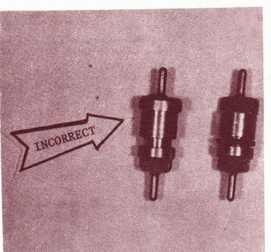
Figure 4 correct and incorrect pump control pistons
  1. Will Not Trim Up Under Load Or Will Not Tilt
    1. Trim up relief valve
    2. Manual release
    3. Trim cylinder-sleeve O-rings piston seals
  2. Will Not Tilt or Trim Down
    1. Trim down pump relief valve ***
    2. Manual release
    3. Impact sensor valve
    4. Filter valve seat
    5. Pump control piston not opening trim check valve
    6. Trim check valve plugged
    7. Worn oil pump
    8. Hydraulic lock †

* Our experience has shown that leak down in the trim range will probably be due to fluid leaking past trim pistons, especially on earlier V-6 trim and tilt units. This is often due to worn trim cylinder sleeves. When the trim fluid has metallic particles in it be sure to drain and refill the unit. Improved hard anodized sleeves are being used in the later trim cylinders.

** Leaking up in trim position with the engine in reverse is usually caused by a leaking impact sensor valve. Inspect the ball and seat closely for damage or foreign material which will hold the valve open.

*** Failure of the engine to trim down with the pump running in the down function is often due to leakage around the trim down pump relief valve so check it first.

† See sample problem - Page 5.

NOTE: Whenever the pump filter is removed and cleaned be sure to soak it in trim fluid and refill cavity before assembly to prevent “air lock”.

There have been a few reported cases of stalling or jam up during the up function. Some failures were caused by an incorrectly manufactured pump control piston. It is located behind the reverse lock check valve. See Figure 4 showing difference between correct and incorrect pump control pistons.

NOTE: The locking lever rod can cause damage to the tilt/trim wiring harness on 1976 and early 1977 models, if the motor is not tilted fully before the locking lever rod is engaged on the stern bracket pads. Demonstrate the proper procedure for operating this mechanism to the customer. Consider installing the 323145 starboard stern bracket which prevents the locking lever rod from damaging the wiring.
PAGE 4SERVICE BULLETIN #1446JOHNSON OUTBOARDS, DIVISION OF OUTBOARD MARINE CORPORATION, WAUKEGAN, ILLINOIS 60085

B. Amperage Reading for Trouble Shooting

The amperage readings can also be valuable aids in troubleshooting the tilt/trim system. Use a D-60 D.C. ammeter connected between the positive (+) battery terminal and the heavy red cable connected to the trim/tilt solenoid. While observing the ammeter, operate the trim switch in both the up and down modes and compare the readings with those given in Figure 5.

NOTE: When using the amperage draw test be sure that the battery is fully charged. The specific gravity of the electrolyte equals or exceeds 1.260 at 80 F (27 C). We recommend a 12 volt battery with a 360 amperes cold cranking rating at 0 F (-18 C) and 115 minutes reserve capacity rating at 80 F (27 C) (70 ampere hour reference).

The specifications contained in this chart are based on standard requirements of the power trim/tilt on an outboard.

CycleNormal Approx. Current Draw (Amps)Approx. Time in Seconds
Trimming Up236
Tilting Up275
Full Tilt Up44-
Tilting Down205
Trimming Down207
Full Trim Down29-

Figure 5

The following table will help in analyzing the current draw of the pump motor:

Normal Current Draw - Normal maximum current draw in the up or down modes (44 amps up/29 amps down) indicated the hydraulic pump is developing full output pressure. Check the following items for possible defects:

  1. Mechanically jammed pistons or rods.
  2. Pump control piston stuck or jammed.
  3. Check valve, no opening or plugged
    1. Reverse lock check valve (can effect up or down movement)
    2. Trim check valve or hydraulic lock - see sample problem, Page 5 (effects down movement only)
    3. Tilt check valve (effects up movement)
  4. Trim check valve hydraulically locked - see sample problem, Page 5.

Low Current Draw - Lower than maximum current draw in the full up or full down modes (less than 44 amps up or less than 29 amps down) indicates the hydraulic pump is not developing the required system pressure. Check the following items:

PAGE 5SERVICE BULLETIN #1446JOHNSON OUTBOARDS, DIVISION OF OUTBOARD MARINE CORPORATION, WAUKEGAN, ILLINOIS 60085
  1. Valves not seating
    1. Trim up relief valve (affects up movement only)
    2. Impact letdown valve (affects up movement only)
    3. Trim down pump relief valve (affects down movement only)
    4. Filter valve (affects down movement only)
    5. Impact sensor valve (affects down movement only)
    6. Tilt cylinder piston head ay. (affects down movement only)
    7. Check balls in the hydraulic pump not seating (can affect up or down movement)
    8. Manual release valve (can affect up or down movement)
  2. Defective valve o-rings - Damaged o-rings on the small end of a valve will result in leakage past the valve seats. Always use new o-rings when installing valves to insure effective sealing around the valve seat.

High current draw - Higher than maximum current draw in either full up or full down position could be the result of:

  1. Trim/tilt electric motor - Remove the electric motor from the manifold assembly and test the current draw of the electric motor only. Maximum current to the motor should not exceed 18 amps.
  2. Hydraulic pump - It is possible for the pump to bind while operating in one direction but move freely when rotation is reversed. Check for binding by rotating the pump in both directions using your finger or a screwdriver to turn the drive coupling. If more than 36 inch ozs. is required to turn the pump (more than can be applied using fingers) replace the pump.
  3. Relief valve not opening at correct pressure - Trim up relief valve should open at 1500 P.S.I. (44 amps) and the trim down pump relief valve should open at 800 P.S.I. (29 amps).

SAMPLE PROBLEM: The power trim/tilt will raise the motor from partial to full tilt up position, and the motor will remain tilted with no leak down observed. When the down button is depressed the motor will not move down and the current draw of the trim/tilt electric motor is 29 amps.

ANALYSIS: Since the current draw measured for down movement is the maximum allowed for full down trim (29 amps), we can assume the normal hydraulic pressure is available, and can eliminate the following items:

  1. Trim down relief valve - opening at 800 P.S.I.
  2. Impact sensor valve - sealing ok.
  3. Filter valve - sealing ok.
  4. Manual release valve, and o-rings for the pistons and check valves, the seals are working ok since no leakdown was observed.
  5. Reverse lock check valve - is opening and allowing fluid to return to the pump from the top sides of the tilt piston during up movement.
PAGE 6SERVICE BULLETIN #1446JOHNSON OUTBOARDS, DIVISION OF OUTBOARD MARINE CORPORATION, WAUKEGAN, ILLINOIS 60085

We have now narrowed the cause of this problem to 3 items.

  1. Pump control piston - if the control piston is stuck into the reverse lock check valve, the trim check valve will not be opened for all hydraulic fluid to return to the reservoir from the bottom of the trim/tilt pistons.
  2. Trim check valve - If the pump control piston does not open the trim check valve, or if the valve is plugged, hydraulic fluid will not return to the reservoir from the bottom of the trim/tilt pistons which will prevent the pistons from moving downward.
  3. Hydraulic lock - Excessive pressure behind trim check valve, normal pump pressure cannot open trim check valve. Caused by motor bouncing while trailering partially tilted. One trim cylinder end cap may be loosened 1/4 turn to relieve pressure. Tilt down, then up momentarily and retorque end cap to restore normal operation. To avoid problem do not trailer partially tilted.

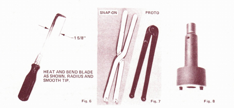
When the trim cylinders need replacing a bent screwdriver will get the task accomplished quickly and easily. Place the screwdriver blade under the lip of the trim cylinder sleeve and pull up to remove. See Figure 6 for suggested maximum dimensions.

Figures 6 through 8: bent screwdriver, spanner wrenches, socket type spanner

The Snap-On and Proto spanner wrenches in Figure 7 will remove the tilt and trim cylinder end caps. Other suitable spanners are available. When an end cap is seized in a cylinder use a socket type spanner to loosen it. See Figure 8.

JOHNSON OUTBOARDS

D. J. Leinonen
Technical Data Coordinator

DJL/vn

NOTE: Post on the 70 thru 200 hp. indexes under heading “miscellaneous” and on the Miscellaneous Index under heading “Accessories”.

PAGE 7SERVICE BULLETIN #1446JOHNSON OUTBOARDS, DIVISION OF OUTBOARD MARINE CORPORATION, WAUKEGAN, ILLINOIS 60085
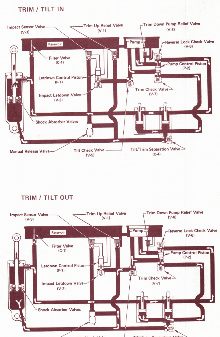
Factory hydraulic schematics: TRIM / TILT IN and TRIM / TILT OUT, showing pressure and flow paths

Factory hydraulic flow schematics: TRIM / TILT IN and TRIM / TILT OUT.

PAGE 8SERVICE BULLETIN #1446JOHNSON OUTBOARDS, DIVISION OF OUTBOARD MARINE CORPORATION, WAUKEGAN, ILLINOIS 60085
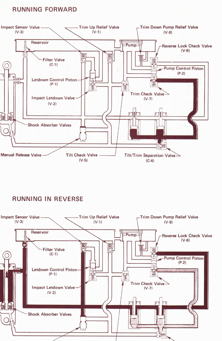
Factory hydraulic schematics: RUNNING FORWARD and RUNNING IN REVERSE, showing pressure and flow paths

Factory hydraulic flow schematics: RUNNING FORWARD and RUNNING IN REVERSE.