SB-1483 - Remote Control Wire Shorting
Issued in October 1978, this Johnson Service Bulletin describes a replacement procedure for ignition shutoff wire insulation on certain early-production 1979 remote controls used with 55 through 235 H.P. outboards.

SB-1483
OCTOBER 1978
SUBJECT: REMOTE CONTROL WIRE SHORTING
MODELS: 1979 EARLY PRODUCTION 55 THRU 235 H.P.
We have learned that some of the insulating sleeves of the black/yellow striped ignition shut off lead used on production remote control ignition switch may transmit a small amount of current resulting in an ignition miss or hard starting condition. This sleeve must be replaced.
Remote controls with a new nonconductive sleeve may be identified by the “XX” stamped next to the part number on the remote control shipping carton. The white sleeve on the large red positive battery lead has also been marked with red to indicate the insulating sleeve has been replaced.
On any remote control installed or still in dealer stock without the “XX” marked on the control carton, the insulating sleeve on the ignition shut off wire must be replaced with heat shrink tube P/N 510628.
The following procedure should be followed to replace the insulating sleeve and a claim submitted for one hour’s labor.
*1. Remove remote control from boat or from shipping carton.
3. Loosen the nut securing the ignition switch and lift switch out of remote control. See Figure 2.
2. Remove the three access cover to housing screws. See Figure 1.
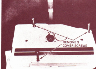
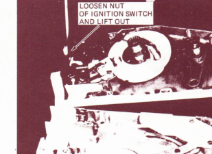
*NOTE: If remote control is in boat, disconnect positive (+) battery cable before removing control.
PAGE 2
SERVICE BULLETIN 1483
JOHNSON OUTBOARDS, DIVISION OF OUTBOARD MARINE CORPORATION
4. Remove the screw securing the ignition shut-off lead (black/yellow stripe). See Figure 3.
6. Install heat shrink tube P/N 510628 over terminal on wire and shrink by heating with a match flame. See Figure 5.
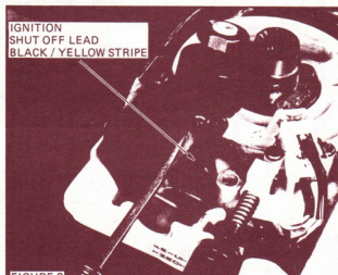
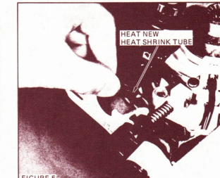
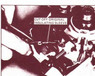
5. It is absolutely essential that the original insulating sleeve be removed. Being careful not to cut through the insulation of the black/yellow stripe wire, cut the insulating sleeve and remove. See Figure 4.
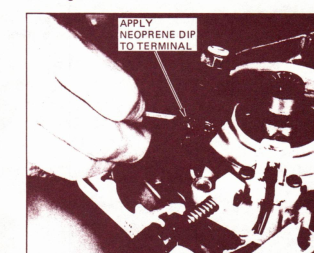
7. Reattach terminal of wire to ignition switch and coat terminal with OMC Neoprene Dip P/N 909570 or Gaco Neoprene Dip P/N 315417 or equivalent, to insure protection from corrosion. See Figure 6.
8. Reassemble remote control and reinstall. Mark white sleeve on red positive battery cable with red marker to indicate this procedure has been completed.
NOTE: Post on 55 thru 235 indexes under heading “Electrical”.
CR 78-71