Johnson Service Bulletin SB-1490 (February 1979) - Corrections to 1979 Service Manuals

Factory corrections to 1979 Johnson service manuals for 6 through 235 HP engines, including carburetor, crankcase, torque, and special-tool specifications.

Johnson Service Bulletin letterhead
SB-1490

February, 1979

SUBJECT: CORRECTIONS TO 1979 SERVICE MANUALS

Enter the following corrections to the Service Manuals in each book as stated to keep your Service Manuals correct for future reference.

6 HP

pg. 7-5

Should read: “Wind pinion gear about 12-1/2 turns in a counterclockwise direction until rope knot lug is accessible for inserting rope.”

9.9 - 15 HP

(1) pg. 2-2

1. Change high speed orifice (9.9 HP) #322752 #38 to #321742 #40 jet. 2. Change high speed orifice (15 HP) #323642 #50 to #322293 #54 jet. 3. Change inlet needle seat size from 0.065 - 0.062 to 0.053 - 0.050.

(2) pg. 3-3

Shims have been added to the 15 HP model and fit between the leaf valve and leaf stop.

(3) pg. 6-20

Figure 6-65 should read: “Shorten link two turns after alignment with hole in shift lever.”

25 - 35 HP

(1) pg. 2-3

1. Crankshaft end play was changed from 0.011 max. - 0.003 min. to 0.025 max. - 0.000 min. 2. The water flow diagram is incorrect. A new chart is attached to this correction sheet.

55 HP

(1) pg. 2-8 5-Adjust Choke Solenoid

Step B should read: “Move solenoid down until terminal block is against the solenoid clamp. Next, tighten the clamp screws.”

(2) pg. 2-2 Specifications

Should read: High speed orifice plug P/N 322907; Idle orifice plug (top carburetor) P/N 323151, hole size 0.045 (1.125 mm); (bottom carburetor) P/N 325827, hole size 0.044 (1.12 mm).
(3) pg. 3-12

Last sentence in first column should read: “Follow the instructions given in Section 2, ‘Engine Synchronization and Adjustments’.”

(4) pg. 4-20 Installation - Step A.

Add “Using OMC Screw Lock (P/N 384848) on coil screws, torque 4 to 5 ft. lbs.”

(5) pg. 5-15 Crankcase and Cylinder - Step A.

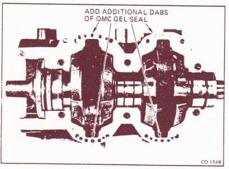
Should read: “Clean the crankcase flange with OMC Cleaning Solvent (P/N 390905). Squeeze out a 1/4” (6 mm) ball of Gel Seal and dab it along one crankcase flange. Add additional Gel-Seal in small dabs to the outer edge of the surface.” See Figure CO 1548.

70 - 75 HP

(1) pg. 2-14 5-Adjusting Choke Solenoid

A. Should read: “With manual choke lever in ‘off’ position, loosen solenoid bracket screws and push solenoid back until it contacts the boss on the engine block.” B. Should read: “Tighten solenoid bracket screws.”

(2) pg. 3-10 Leaf Valves - Paragraph B.

Add sentence: On the 75 HP model the leaf stop shims fit on both sides of the leaf block.

(3) pg. 5-11 Pistons

The last two sentences of first paragraph should read: “Replace the piston if variation in diameter at the bottom of the piston skirt is greater than 0.004 inch (0.10 mm).”

(4) pg. 5-15 Crankcase and Cylinder - Step A.

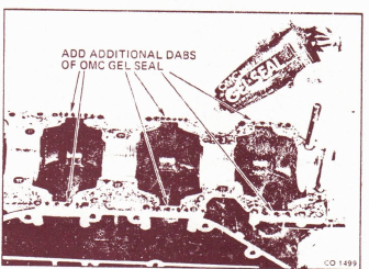
Should read: “A. Clean the crankcase flange with OMC Cleaning Solvent (P/N 390905). Squeeze out a 3/8” (10 mm) ball of Gel Seal and dab it along one crankcase flange. Add additional Gel Seal in small dabs to the outer edge of the surface. Keep it 1/4” (6 mm) away from each labyrinth seal. Treat the other crankcase flange the same way.” See Fig. CO 1499.

Original Johnson factory illustration co-1548Original Johnson factory illustration co-1499
(5) pg. 6-26 - Step P.

Special tool P/N 417061 is not correct and should be changed to P/N 317061.

V-4 Models 85 thru 140 HP

(1) pg. 2-2 Specifications

Carburetor low speed orifice plug for the 140 HP should be P/N 317473, hole size 0.030 (0.76 mm).

(2) pg. 2-5 Torque Chart

Trim Cylinder Endcap - 35-40 ft. lbs. (40-54 N·m)

(3) pg. 5-1 OMC Special Tools Required

Ring Compressor Standard should be P/N 316655 instead of P/N 308867. (Note same change on page 5-24 - Piston-Connecting Rod Installation)

(4) pg. 5-29 Crankcase and Cylinder - Step A.

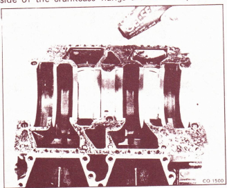
Should read: “Clean the crankcase flange with OMC Cleaning Solvent (P/N 390905). Squeeze out a 3/8” (10 mm) ball of Gel Seal and dab it along both sides of crankcase flange. Add additional Gel Seal in small dabs to the outer edge of the surface. Keep it 1/4” (6 mm) away from each labyrinth seal. Treat the other side of the crankcase flange the same way.” See Figure CO 1500.

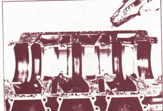
Original Johnson factory illustration co-1500Original Johnson factory illustration co-1501
(5) pg. 6-21 - Step I.

Change Special Tool P/N 387206 to P/N 390706.

(6) pg. 6-32 Shift Rod Height Gauge

Part Number should read P/N 389997.

(7) pg. 9-16 Trim Cylinders

Trim Cylinder Sleeve Remover (OMC P/N 325065) not 324958.

V-6 Models 150 thru 235 HP

(1) pg. 2-4 Torque Chart

Trim Cylinder Endcap - 35-40 ft. lbs. (47-54 N·m).

(2) pg. 2-15 8. Synchronize throttle and timer linkage.

Step B should read: “Start motor and advance control box warm-up lever to show 6° to 8° advance timing.”

(3) pg. 5-18 Pistons

The first two sentences should read: “Check the pistons for roundness, excessive skirt wear, and scoring. Replace the piston if variation in diameter at the bottom of the piston skirt is greater than 0.004 in. (0.10 mm).”

(4) pg. 5-26 Crankcase and Cylinder - Step A.

Should read: “Clean the crankcase flange with OMC Cleaning Solvent (P/N 390905). Squeeze out a 3/8” (10 mm) ball of Gel Seal and dab it along one crankcase flange. Add additional Gel Seal in small dabs to the outer edge of the surface. Keep it 1/4” (6 mm) away from each seal ring surface. Treat the other crankcase flange the same way.” See Figure CO 1501.

(5) pg. 6-5 - Step d.

Should read: “Remove shift rod connector screw.” See Figure 6-4.

(6) pg. 6-20 - Step i.

Change OMC Special Tool P/N 387206 to 390706.

(7) pg. 6-21 - Step m.

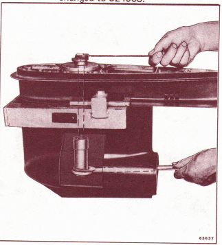
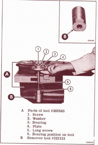
If necessary, remove lower driveshaft bearing using Bearing Remover (Special Tool P/N 321521) and components of OMC Special Tool P/N 385546. See Fig. 6-57 & 6-58. Replace Fig. 6-57.

(8) pg. 6-22

Replace Figure 6-58.

(9) pg. 6-27 - Step b. The Shim Gauge

Special tool P/N 315767 should be changed to P/N 321520. Shim tool P/N 315767 is for the V-4 models only, and shim tool P/N 321520 is for the V-6 models only.

(10) pg. 6-30 In the Shift Rod Connector

Adjustment procedure, the second sentence in Step B, should read: “Standard length gearcase should be 22 & 1/16 ± 1/32 (560.39 ± 0.31 mm). Long shaft model should be 27 & 1/16 ± 1/32 (687.39 ± 0.31 mm).” Shift Rod Heights Gauge part number should read P/N 389997.

(11) pg. 9-14 Trim Cylinders

The Trim Sleeve Remover, OMC P/N 324958, should be changed to P/N 325065. This is in the second last sentence in the paragraph.

(12) pg. 9-15 Figure 9-21

The tool number 324959 should be changed to 324958.

Original Johnson factory illustration fig-6-58Original Johnson factory illustration fig-6-57

Figure 6-58. Removing Pinion Bearing. Figure 6-57. Pinion Bearing Remover Set-up.

CR 78-72 © OUTBOARD MARINE CORPORATION 1979 ALL RIGHTS RESERVED

Note: Post on The Miscellaneous Index under the heading “Service Procedure Change.”

Related reference: 1970-1980 Johnson Service Bulletin Index.