OMC Service Bulletin No. 2009 - Erratic Alternator Tachometer Operation - Defective Rectifier
OMC bulletin on diagnosing erratic alternator tachometer readings caused by a defective rectifier.

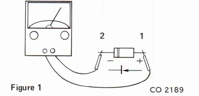
There have been cases where the alternator tachometer operation has been erratic due to high resistance in the rectifier bridges. First it must be determined, what the polarity is of the meter being used. With the Ohmmeter set on 1k scale, apply the two leads across a known good diode as shown in Figure 1.
If the needle moves and shows a resistance, then the lead of the meter at point (1) is positive (+) and the lead at point (2) is negative (-) and should be marked as such. If the meter shows no reading (infinity), then reverse the leads of the meter across the diode so it will read continuity. Then mark the meter leads (+) and (-).
Check the bridges at air temperature first, then heat the rectifier between 175°F and 200°F (with a heat gun or in a pan of hot water) and measure the forward resistance. Check each diode in rectifier. Figure 2 shows one diode being checked.
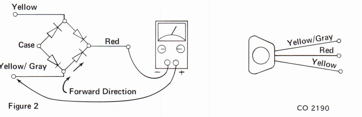
When the rectifier is heated, the resistance may increase (needle of meter will move up scale). Should this happen replace the rectifier.