OMC Service Bulletin No. 2033 (January 1982). Historical factory guidance on Economixer oil-injection operation, warning indicators, and troubleshooting.
OMC Outboard Service Bulletin header
Accessories
No. 2033
January, 1982

Subject: OMC Economixer™ Operation and Troubleshooting

The OMC Economixer oil injection system provides a regulated amount of oil to an engine. The oil is injected into the engine fuel supply line to provide a ratio of gasoline to oil that varies with engine demand. At slow speed the engine requires very little oil. At higher speeds and heavier load conditions the engine requires a greater amount of lubrication.

A throttle position sender connected to the carburetors and lead wire connected to the engine alternator sends signals to a microcomputer in the Economixer pump assembly. The microcomputer reads these signals and causes the oil pump to pulse at the correct rate to satisfy engine demands.

A gauge on the boat instrument panel tells the boat operator that the system is ready to operate or that there is a problem.
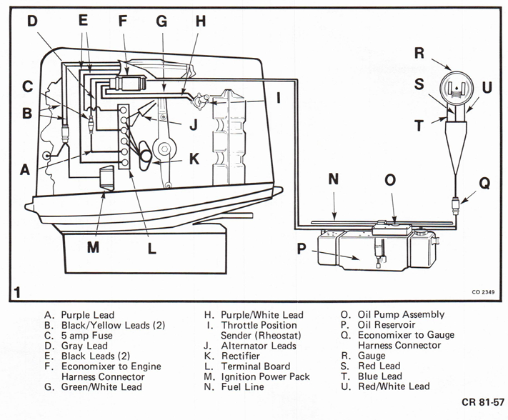
OMC Economixer wiring and component diagram with A-U legend
CR 81-57

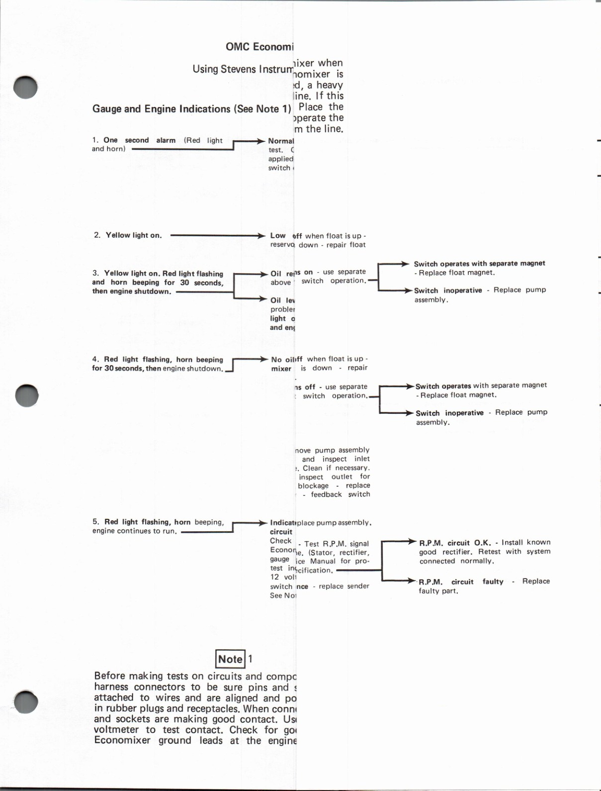
When the key switch is turned to the “on” position, the gauge alarm horn will sound for one second and a red light in the gauge will flash. This indicates that the Economixer microcomputer is checking its systems. Then the pump primes and is ready to operate. If a fault is detected, the red light and horn will alert the operator.

The yellow light, operated by a float, indicates a low oil level in the reservoir. Adding oil to raise the level above 1/3 full should cause the light to turn off. If the light remains on, further troubleshooting will be necessary.

Continuing to run the engine until the oil reservoir is completely empty will result in a gauge display including the yellow light, flashing red light and “beeping” horn. The alarm will last for 30 seconds, then the engine will stop.

If the red light begins flashing and the horn begins “beeping” 30 seconds after the keyswitch has been turned “on,” the oil pump has not primed. The cause could be an empty oil reservoir coupled with a burned out gauge yellow light, a blocked inlet screen or a disconnected pick-up hose on the pump. Other causes would be located by further troubleshooting.

A problem in the throttle position rheostat circuit or R.P.M. sensor circuit is indicated by the red light flashing and horn “beeping.” The alarm will begin operating either immediately after starting the engine or, if the problem develops while the engine is running, when the fault occurs. These conditions cause the Economixer to go into a “back up mode” that results in rapid pump operation and a very rich oil mixture.

No oil flow from the oil pump causes the red light to flash and the horn to “beep” in the “back up mode” for 30 seconds, then the engine is shut down. The engine can be restarted immediately and will run for 30 seconds before the alarm comes on for 30 seconds, then the engine again shuts off. This sequence can be repeated indefinitely.

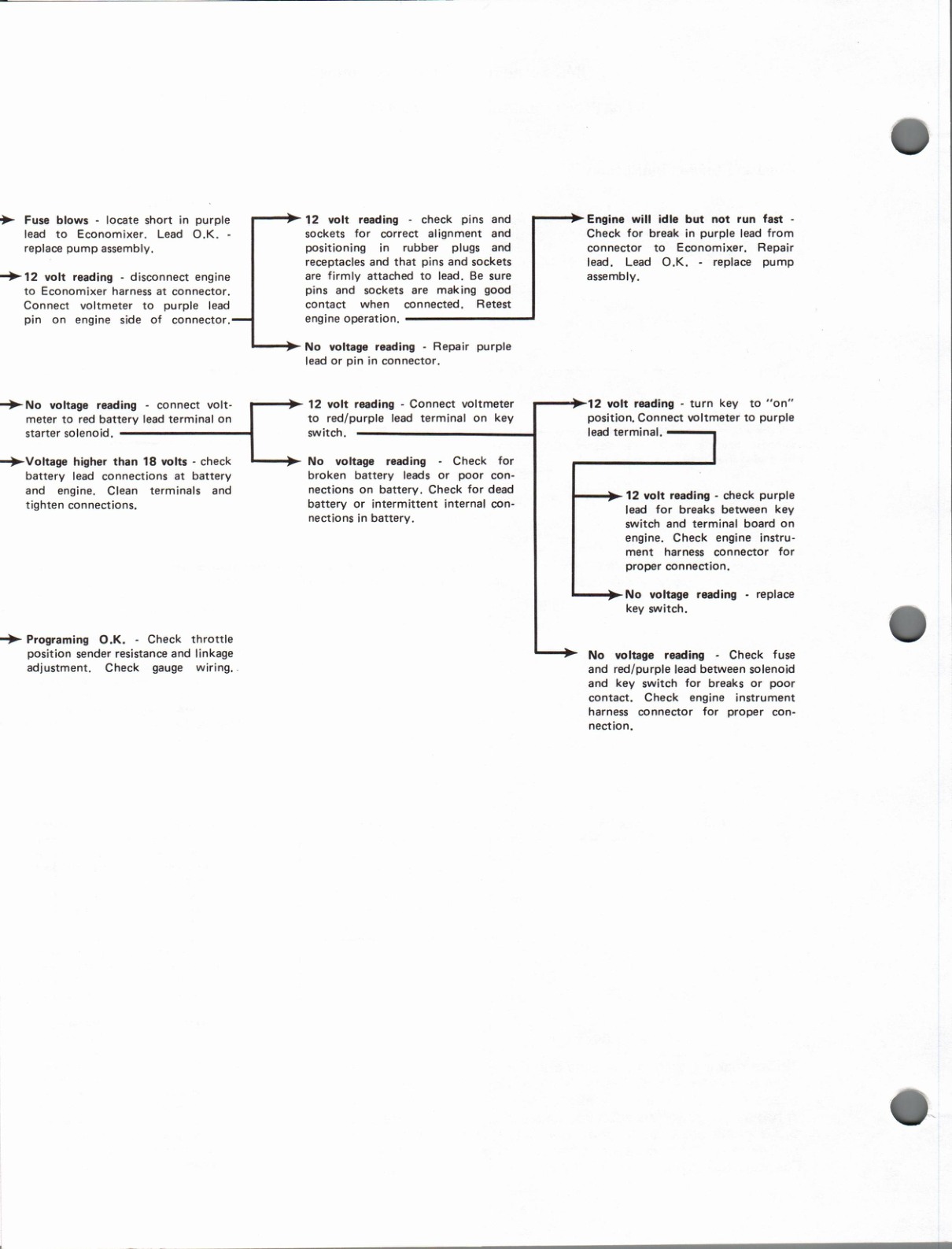
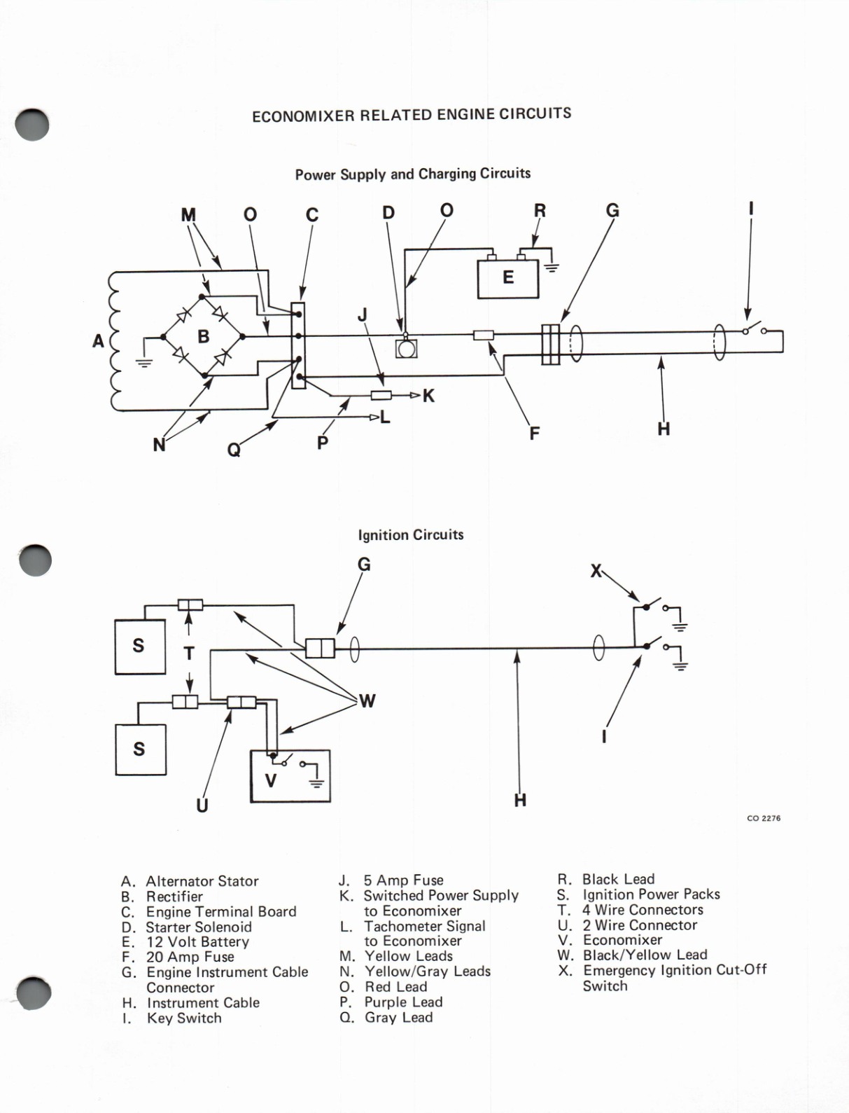
Very high, very low or no voltage in the power supply to the Economixer will not be indicated on the gauge, but will cause the Economixer to affect the engine ignition system. The effect is that the engine can be run at idle but cannot be accelerated to a higher speed. This condition can result from a number of electrical circuit problems such as corroded or broken battery leads and connections, broken power supply leads to the Economixer, blown 5 amp fuse in Economixer lead or the 20 amp fuse in the engine wiring harness, poor or intermittent connections in the engine instrument harness connector, poor or intermittent connections at the key switch and a faulty rectifier on the engine. Figure 2 is a diagram of these circuits and components.

Other problems the gauge will not indicate can show up in the appearance of the engine cylinders and pistons and cylinders of an engine can be damaged by a lack of programming or malfunction of the pump control unit.

The Economixer can be programmed so that it will supply the correct gasoline to oil mixture to 1980 and later V-4 and V-6 outboards or all OMC Sea Drive models. Programming for a particular engine is done in the pump control unit by connecting two wires to terminals designated for that engine.

Original factory bulletin page 3, complex technical material
Original factory bulletin page 4, complex technical material
Original factory bulletin page 5, complex technical material