
Subject: Incorrectly Wired Terminal Block
Models: CO - 65 Com., 70 and 75 Manual Tilt and Power Trim/Tilt Models
Inspect the terminal block of the above models. If necessary change the wire location to correspond with one of the following illustrations.
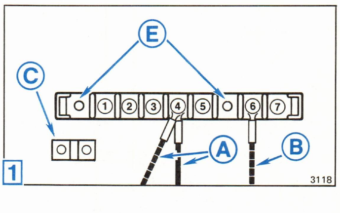
1Manual tilt models:
Terminal 4 - red leads A, connect the rectifier to starter solenoid.
Terminal 5 - not used
Terminal 6 - red/purple lead B, engine harness to terminal block. Jumper bar C between terminals 4 and 5 is not used in this application. Remove and discard.
E Terminal block mounting screws
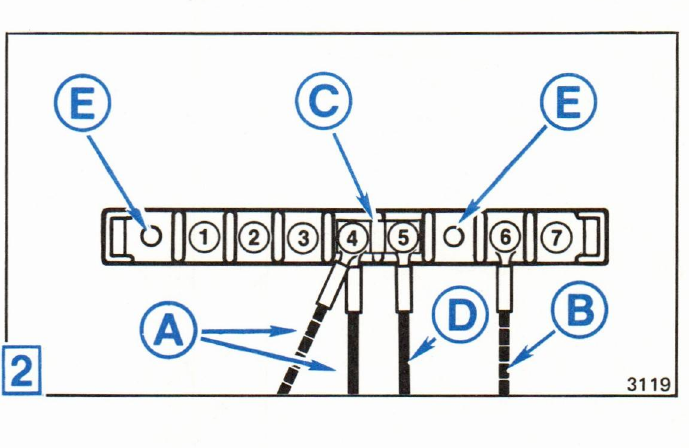
2Power trim/tilt models:
Terminal 4 - red leads A, connect the rectifier to starter solenoid.
Terminal 5 - red lead D, terminal block to junction box.
Terminal 6 - red/purple lead B, engine harness to terminal block. Jumper bar C connects terminals 4 and terminal 5 together.
E Terminal block mounting screws
After making correction, apply OMC Black Neoprene Dip to all terminal connections.
Be sure the decal on terminal block cover corresponds with wire location in the terminal block. If necessary, discard incorrect terminal block cover and decal assembly, and order one of the following:
- 65 Com., 70 and 75 manual tilt models - order terminal block cover P/N 395354.
- 70 and 75 power trim/tilt models - order terminal block cover P/N 396536.