OMC Service Bulletin No. 2239-rev-1 - Stiff or Inoperative Trim/Tilt Switches
June 1991 revised instructions for replacing the trim switch retainer in concealed side-mount remote controls.

Disassembly
⚠ 1. Disconnect battery cables at battery before servicing electrical systems. Failure to do so could result in injury from contact with moving parts, if the engine is accidentally cranked or started.
2. Move control handle to the Neutral detent position. Disconnect the throttle cable at the engine.
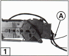
1 3. Cut tie strap securing trim switch leads to remote control body. Disconnect the trim switch wires from the trim cable connector.
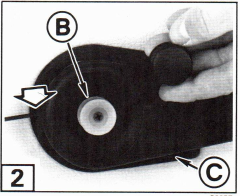
2 4. Remove the rubber boot from the warm-up knob. Remove warm-up knob retaining screw and knob.
5. Disconnect the throttle cable at the motor.
2 6. Move control handle to the full throttle Reverse position. Loosen the set screw retaining the handle. Remove the control handle.
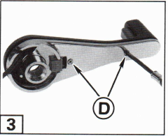
3 7. Remove the two cover retaining screws, and separate the cover from the handle.
(Continued)
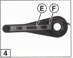
4 8. Remove the neutral rod lockout spring and the neutral rod lockout handle. Wear safety glasses and use caution when removing shift rod lockout handle and spring. The lockout spring is compressed and may fly out causing personal injury.
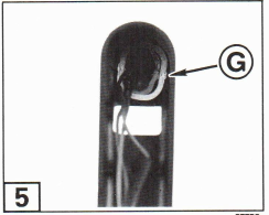
5 9. Remove and discard switch retaining clip. Be careful not to gouge the handle cover. Pull switch and leads out of control handle.
Assembly
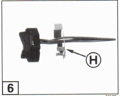
6 1. The wires that are molded into the trim switch are off-center. Position the wires toward the top of the handle and install switch into the cover. Install the improved retaining clip by pushing it into the switch recess until it seats.
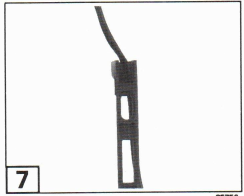
7 2. Insert trim/tilt leads through hole in lockout lever as shown.
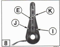
8 3. Insert the blue wire into the slot in the cover at two places. Insert the red and green wire into the slots on the opposite side as shown.
8 4. Reinstall the lockout lever and lockout spring. Wear safety glasses and use caution when installing shift rod lockout handle and spring. The lockout spring is compressed and may fly out causing personal injury.
3 5. Route trim switch harness through handle cover opening. Attach cover to control handle and retain with two screws. Tighten screws securely.
6. Route trim/tilt switch harness through opening in gunnel of boat.
2 7. Reinstall control handle assembly in Reverse position. Torque set screw to 25-35 in. lbs. (2,8-4,0 N-m).
2 8. Reinstall warm-up knob and screw. Tighten screw securely. Reinstall rubber boot over warm-up knob.
1 9. Loop trim wires loosely around control body. Secure loop and neutral start wires to strain relief hole (in neutral start switch shield) with a tie strap.
10. Attach the throttle cable to the engine.
11. Reconnect battery cables. Check for proper trim function. Check that remote control handle operates freely, and that warm-up function works properly.
Submit a warranty claim for repairs performed within the 1 year limited warranty. List Flat Rate Code as R-13 for a time of 1 hour. List the failing part as P/N 126263. List P/N 126565 as the part used in repair.
⚠ Safety Related
Related marine products
Amazon: Marine battery cable
Related marine supplies
eBay: OMC / Evinrude part 174930
Listings matching the part number
Affiliate disclosure: EverythingOutboards may earn a commission from qualifying purchases. As an Amazon Associate, we earn from qualifying purchases.
Related products
Trim/tilt switch retainer P/N 126565 - recommendations coming soon.