OMC Service Bulletin No. 2244 - Troubleshooting the Touch-Trim Trim System

Published October 1991, this five-page bulletin covers operation, pre-delivery checks, cable and lever adjustment, and hydraulic-unit troubleshooting for Touch-Trim systems on 1989 and newer 40, 48, and 50 outboards.

OMC Outboard Service Bulletin factory header
Midsection

No. 2244
October, 1991

Subject:Troubleshooting the Touch-Trim™ Trim System
Models:1989 and Newer 40, 48, and 50

THE TOUCH-TRIM™ SYSTEM AND HOW IT OPERATES

The Touch-Trim™ trim system is:

  • A gas charged hydraulic cylinder that counter-balances the weight of the motor.
  • A one-way hydraulic shock absorber that controls the tilt of the motor if an under water object is hit at high speed.
  • A lever that is connected by adjustable cable to a valve that opens to allow the motor to raise and lower and closes to hold motor in any position.

PRE-DELIVERY CHECKS

  • Check If Unit Supports Motor
  • Check Cylinder Rod For Paint
  • Check Torque On Tilt Tube Nut
  • Check Cable For Freedom of Motion
  • Check Lever For Freedom of Motion
  • Check Lever Reserve Motion

Making these checks before delivering each new motor will ensure customer satisfaction and longer, trouble-free service.

TROUBLESHOOTING OPERATING PROBLEMS

•  Check If Unit Supports Motor

There must be enough gas pressure to approximately balance the motor in any tilted position.

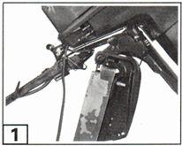
1 With motor on transom or stand OPEN the valve, and tilt motor about half way up. Motor should stay in any tilted position with the valve open.

If motor drops when you release it, replace the hydraulic unit. For procedure see OMC® Service Manual, “EI” ('91) or newer.
Factory illustrations for bulletin page 1

•  Check Cylinder Rod For Paint

The cylinder rod must be free of paint and scratches which would damage the seal, and let the gas pressure escape.

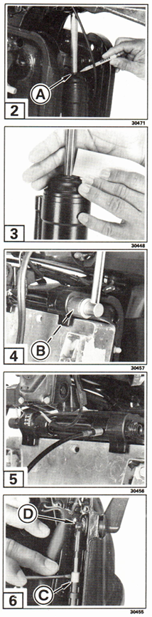
2 Extend cylinder completely. Inspect cylinder rod for scratches or paint, particularly next to seal A.

3 Carefully scrape off any paint with a non-metallic scraper. Do not use a hard scraper. Scratches are as damaging as paint. 000 steel wool or a soft scrubber can also be used to remove paint. Use crocus cloth to polish out any scratches that have not already caused a loss of pressure. Do not use sand paper or emery cloth.

•  Check Torque On Tilt Tube Nut

The tilt tube nuts must not be over-torqued, and the bushings must be lubricated, to allow the motor to tilt freely.

4 Loosen one tilt tube nut B. Retighten nut to 40-45 ft. lbs. (54-60 N·m) torque, and then loosen ¼ turn.

5 Lubricate tilt tube bushings with OMC Triple-Guard® grease.

•  Check Cable For Freedom of Motion

Cable must move easily so operator can open valve and spring will close valve.

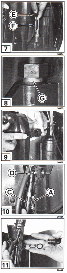
6 Gently pry cable head C out of anchor block and cable end D off lever ball.

7 Loosen nut E, lift cable retainer F, and disconnect cable ball from valve.

8 Safety Warning: If the valve body G starts to unscrew from the cylinder assembly - STOP! Do not continue with troubleshooting. Carefully screw valve body back into cylinder. Replace complete cylinder and cable. Cylinder assembly contains fluid and gas at high pressure. If loosened too much, fluid under pressure will discharge as a dangerous spray. The valve could fly out of the cylinder at high velocity.

Factory illustrations for bulletin page 2
2

9 With cable disconnected at both ends, cable core should move with finger-tip pressure. If cable is not completely free, if it is kinked, or if the jacket is worn thru and the core rusted, replace the cable.

10 Replace Touch-Trim cable following installation instructions with service cable kit and in OMC® Service Manual “EI” ('91) or newer. For initial adjustment thread ball connector D onto cable until cable head C CAN JUST BE PULLED INTO ALIGNMENT WITH ANCHOR BLOCK A with ball connector pushed against ball.

Cycle lever from RUN to TILT 10 times before adjusting cable - See Adjust LEVER RESERVE MOTION.

•  Check Lever For Freedom of Motion

Lever must move freely to allow operator to open valve.

11 With cable disconnected, remove E-ring, washer, and lever. Inspect bearing surfaces on lever and in tiller for burrs. Correct any problem. Lever must turn smoothly in tiller with cable disconnected. Lubricate lever with OMC Triple-Guard® grease, and reassemble.

•  Check LEVER RESERVE MOTION

The LEVER RESERVE MOTION is the amount of lever movement that remains after the valve is closed.

This is a new procedure and replaces the original procedure described in the '89 - '91 service manuals.

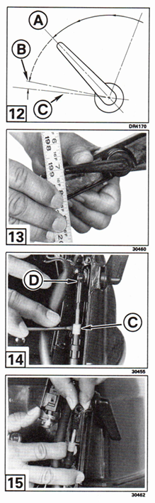
12 To measure LEVER RESERVE MOTION: Start with lever in TILT position and motor tilted up. Move lever to position A, and then slowly move lever toward RUN POSITION C as the motor is slowly tilted down. Valve will first slow the tilting movement, then stop the movement completely. Leave lever in this CLOSED VALVE POSITION B.

To check if the valve is completely closed, leave lever in that position and push down hard on the gearcase. The motor should hold its position.

Factory illustrations for bulletin page 3
3

12 13 Hold a scale next to the end of the Touch-Trim lever and move the lever from the CLOSED VALVE POSITION B to the RUN POSITION C. Measure this distance, the LEVER RESERVE MOTION, which should be about ⅛ inch.

•  Adjust LEVER RESERVE MOTION

The cable must be adjusted so the lever and cable will always let the valve close completely before the lever reaches the RUN position.

14 Gently pry cable head C out of anchor block and cable end D off lever ball.

15 Turn the cable end ONTO the cable (clockwise) TO REDUCE the LEVER RESERVE MOTION, and OFF (counter clockwise) to INCREASE the LEVER RESERVE MOTION. Each half-turn of the cable end changes the RESERVE MOTION by about ⅛ inch. Reconnect cable end to ball, and snap cable head into anchor block.

12 13 Remeasure LEVER RESERVE MOTION and readjust until RESERVE MOTION is ⅛ inch.

If there is insufficient RESERVE MOTION, valve will leak and motor will not lock in either up or down position. If there is excessive RESERVE MOTION, valve may not open enough, and it will be difficult to move the motor.

•  If you run out of threads and cannot remove excess LEVER RESERVE MOTION, the cable liner is worn and cable must be replaced. Newer production cables and all service cables have a greater adjustment range.

•  If LEVER RESERVE MOTION is correct, the tilt tube is lubricated, the torque adjustment is correct, and the unit has the original '89-'90 lever, and if the tilting motion is still slow or feels restricted BOTH UP AND DOWN; replace the lever. New levers (same part number) have a longer stroke.

Factory illustrations for bulletin page 4
4

•  Test Valve

The valve must open and allow fluid to move between the top and bottom chambers for the motor to tilt up and down.

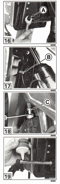
16 17 Remove one tilt pin nut A and tilt pin. Lift motor half way and remove cable from retainer B inside starboard stern bracket. Lift motor and support with tilt lock.

18 With cable disconnected from valve, place screwdriver blade under valve stem connector C and push screwdriver down to pry valve stem up.

⚠ Do not put fingers between hydraulic unit and transom bracket boss. Pressurized unit has sufficient force to cause injury.

A small push down on screwdriver should cause a small movement down (extension) of the hydraulic unit. Opening the valve fully should cause more rapid movement. If hydraulic unit does not extend when valve is opened, or does not extend all the way, replace hydraulic unit.

•  Replace Hydraulic Unit

If hydraulic unit does not perform as it should, replace it.

⚠ Do not disassemble hydraulic unit. Fluid is under pressure and will discharge as a dangerous spray. No detail parts are available and unit is not serviceable.

Note Carefully check cylinder rod on new hydraulic unit. Remove any paint, etc. before unit is installed. If unit is to be painted to match motor, rod must be masked completely, with tape covering edge of seal.

19 Reinstall unit using Triple-Guard® grease on both pins. See installation instructions in OMC® Service Manual “EI” ('91) or newer.

Complete PRE-DELIVERY CHECKS (in this instruction) before delivering motor with new Touch-Trim unit.

Factory illustrations for bulletin page 5
5