OMC Service Bulletin No. 2285 - Testing QuikStart™ Timer Bases

Published in August 1994, this OMC bulletin addresses testing quikstart™ timer bases for 60, 70, 185 thru 300.

OMC Outboard Service Bulletin
Ignition
No. 2285
August, 1994
Subject:

Testing QuikStart™ Timer Bases

Models:

60, 70, 185 thru 300

Problem:

QuikStart equipped timer bases have a number of semiconductors that control internal switching functions. This added sophistication causes these timer bases to respond differently to each type of ohmmeter when you perform sensor coil resistance tests. When you perform the sensor coil resistance tests outlined in the service manuals, your test results will vary with the input impedance of each different ohmmeter.

Solution:

When you perform a resistance test on a circuit that includes semiconductors, there can be no “right” reading. Your reading will be dictated by the ohmmeter you use.

Resistance values for several specific ohmmeters are listed in your service manuals.

Important Remember that your test results will not match the service manual values unless you use one of the ohmmeters listed and it has fresh batteries. When testing QuikStart sensor coils with an ohmmeter, all your resistance readings should be approximately equal, regardless of which ohmmeter you use.

Note A copy of the page describing sensor coil resistance tests for 1995 90° V6 engines is included with this bulletin for your reference.
Sensor Coil Ohmmeter Test

Note All ohmmeter tests must be performed with engine not running.

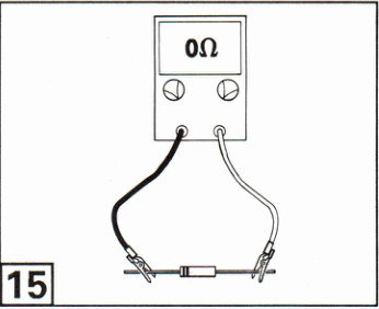
15 1. Before proceeding, you must verify that the ohmmeter red lead is the “+” lead. Calibrate meter on appropriate scale. Attach to a known good diode as shown.

  • Meter must show a low reading.
  • When meter leads are reversed, meter must show a high reading.

2. If your test results are opposite, reverse internal meter lead connections so the red lead represents “+”.

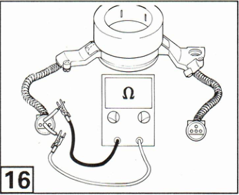
16 3. Attach ohmmeter red lead to port timer base connector, terminal “D”.

16 4. Alternately, attach ohmmeter black lead to port connector, terminals “A”, “B”, and “C”, and starboard connector, terminals “A”, “B”, and “C”. Meter reading at each connection should be:

  • Stevens AT-101 meter: 360 ± 30 ohms
  • Merc-O-Tronic M-700 meter: 950 ± 100 ohms
  • Fluke 29 Series II meter: 975 ± 100 ohms

Note The Fluke 29 Series II meter must be set to the low ohms (40 Ω) scale for this test. Read the operating instructions that came with the meter.

Ohmmeter readings will vary with individual meter impedance. Your readings might be slightly higher or lower, but should all be approximately equal.

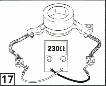
17 5. Attach ohmmeter red lead to port timer base connector, terminal “D”. Attach meter black lead to starboard timer base connector, terminal “D”.

  • Meter should read 230 ± 30 ohms.

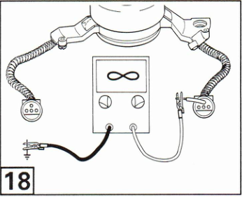
18 6. To test for a grounded condition, connect ohmmeter alternately between each port and starboard terminal location and a clean engine ground.

  • Meter must show a high reading.
  • If meter shows a low reading, locate and repair ground or replace timer base.

7. Complete all circuits disconnected during this test.

Factory figure 15Factory figure 16Factory figure 17Factory figure 18