OMC Service Bulletin No. 2355 - Throttle Cable Installation and Throttle Setting

March 2000 bulletin with the throttle and shift cable installation and adjustment procedure for specified 150/175 FFI outboards.

OMC Technical Service Outboard Bulletin
ROUTE TO:  □ SERVICE MANAGER  □ SERVICE WRITER  □ TECHNICIAN 1  □ TECHNICIAN 2  □ TECHNICIAN 3  □ FILE
Powerhead
No. 2355
March, 2000
Subject:
Throttle Cable Installation and Throttle Setting
Models:
150/175 FFI EE (“O” Suffix) & 150/175 FFI SS (“V” Suffix).
Problem:
Improper running characteristics throughout the RPM range.
Solution:
Perform the following steps in the designated sequence to ensure proper running characteristics.

Connect Control Cables

1 2 Remove screw retaining trunnion anchor. Remove anchor. Insert shift and throttle cables into engine cover.

To gain access, move control to FULL THROTTLE position. Move engine throttle lever to full throttle position. Install throttle guide on throttle lever. Install washer and clip to secure guide.

Note Refer to OMC® FFI™ Diagnostic Software Version 1.41 User’s Guide, P/N 787087, for connection of computer to engine. See Menu Option 4 - Engine Monitoring to view window for following procedure.

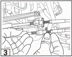
3 With the remote control in NEUTRAL and the fast idle lever down, pull slack from the cable and adjust the throttle trunnion in the pocket until 0.55 volt (TPS Act) is indicated. Move control to FULL THROTTLE and check for failure code 14. If code is indicated, return control to NEUTRAL and reset voltage to 0.45 (TPS Act).

Turn ignition key OFF/ON; 0% open (TPS Cal) should be indicated. If not, turn key OFF/ON until 0% open is achieved.
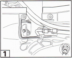
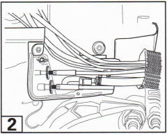
Factory illustration 1Factory illustration 2Factory illustration 3
Factory illustration 4Factory illustration 5Factory illustration 6

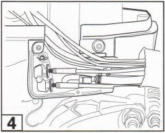
Move control to REVERSE. Move engine shift lever to reverse. Install guide on shift lever. Install washer and clip to secure guide. Move control to NEUTRAL. Hold cable next to trunnion bracket. Trunnion must align with bracket pocket.

4 Hold cables in position and install trunnion anchor and mounting screw.

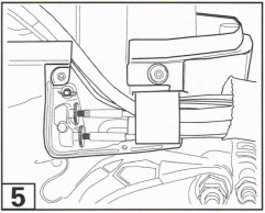
5 Slide sleeve-retaining ring to engine. Make sure bracket is seated against engine cover and tabs hold it in position.

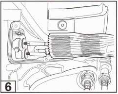
6 Slide ring forward and slide sleeve over retaining ring. Slide sleeve and ring into position.

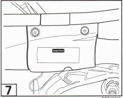
7 Position trunnion cover on lower engine cover. Make sure rib in cover aligns with boss on plastic retainer. Make sure electrical cables and hoses do not interfere with cover and control cables. Tighten screws evenly and securely.

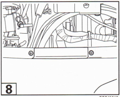
8 Install cables access cover and tighten screws securely.

Throttle Setting

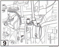
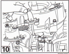
9 Loosen the throttle adjustment screw.

Move the throttle arm lever until 25% open (TPS Cal) is indicated.

Hold the roller firmly against the cam and tighten the roller adjustment screw.

Move the throttle back to 0%, then bring the throttle up to 25%. The cam and roller should be touching.

Test Start-In-Gear-Prevention System

For procedures, refer to OMC Accessory Service Manual, and to Remote Control Installation Instructions.

Important After the installation and all adjustments are completed, the last step must be to recheck and adjust the throttle and shift cables. Any change to the cables, their position, routing, or support, changes the cable adjustment.

Factory illustration 7Factory illustration 8Factory illustration 9Factory illustration 10

Related marine products

eBay: OMC / Evinrude part 787087

Listings matching the part number

Affiliate disclosure: EverythingOutboards may earn a commission from qualifying purchases. As an Amazon Associate, we earn from qualifying purchases.

Related products

Throttle and shift cable service components - recommendations coming soon.