OMC Service Bulletin 2357-rev-1: Throttle and Shift Cable Installation

October 2000 revised OMC procedure for throttle and shift cable installation on 200/225 Ficht Ram Injection outboards.

OMC Technical Service Bulletin
Powerhead

No. 2357, Rev.1
October, 2000

Subject:Throttle and Shift Cable Installation
Models:200/225 Ficht Ram Injection® 2000 (SS).
Problem:Improper running characteristics throughout the RPM range.
Solution:Perform the following steps in the designated sequence to ensure proper running characteristics.

Note Refer to OMC® Service Manual for proper synchronization and linkage adjustments.

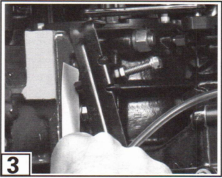
1Remove screw retaining trunnion anchor. Remove anchor. Insert shift and throttle cables into engine cover.

To gain access, move control to FULL THROTTLE position. Move engine throttle lever to full throttle position. Install throttle guide onto throttle lever pin. Install washer and locknut to secure guide.

2Shift the remote control FORWARD and then half way back into NEUTRAL. Pull slack from throttle cable and adjust the throttle trunnion to fit into the bracket pocket.
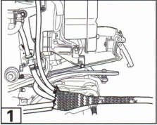
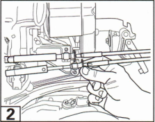
Factory figure 1Factory figure 2

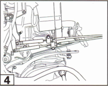
3Hold the cable in position and install trunnion anchor and mounting screw. Torque screw 60-84 inch pounds. Shift control into NEUTRAL. Verify idle stop is seated against block with no free play evident in engine throttle linkage assembly.

4Move control to REVERSE. Move engine shift lever to REVERSE. Install shift cable guide onto shift lever pin. Install washer and locknut to secure guide. Move control to NEUTRAL. Move engine shift lever to NEUTRAL. Hold cable next to trunnion anchor pocket, adjust trunnion to align with the trunnion pocket. Install trunnion anchor and screw while holding shift cable in place. Torque screw 60-84 inch pounds.

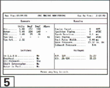
5Use the current version of the OMC® Diagnostic Software engine monitoring screen, verify TPS% shows (0%). If TPS percentage shows any other value, cycle the key switch off/on until 0% is shown.

Check engine to ensure all components are routed so they will not interfere with engine cover installation.

Test Start-In-Gear Prevention System - All Models

For procedure, refer to the OMC Accessory Service Manual, and to Remote Control Installation Instructions.

Important After the installation and all adjustments are completed, the last step must be to recheck and verify proper adjustment of throttle and shift cables. Any change to the cables, their position, routing, or support, could change the cable adjustment and require readjustment.

Factory figure 3Factory figure 4Factory figure 5